

Contact for pricing and lead time--a minimum order quantity may apply
Contact for pricing and lead time--a minimum order quantity may apply
Contact for pricing and lead time--a minimum order quantity may apply

Contact for pricing and lead time--a minimum order quantity may apply
Contact for pricing and lead time--a minimum order quantity may apply
Contact for pricing and lead time--a minimum order quantity may apply
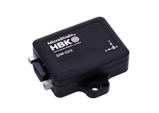
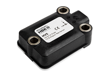
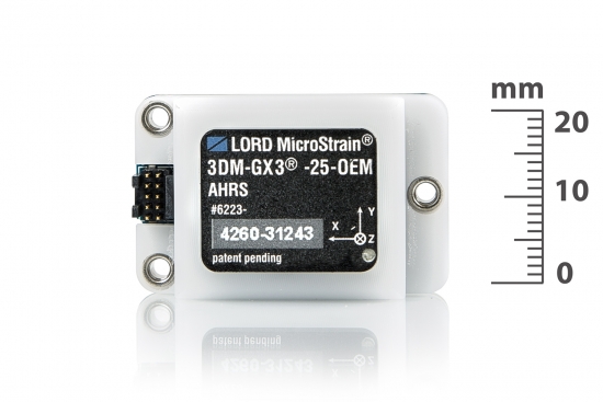
The 3DM-GX3® -25-OEM is a lower cost, miniature, industrial-grade attitude heading and reference system (AHRS) with integrated magnetometers, and OEM form factor.
Product Highlights
- High performance integrated MEMS sensor technology provide direct and computed AHRS outputs in a small package.
- Triaxial accelerometer, gyroscope, magnetometer, and temperature sensors achieve the best combination of measurement qualities.
- On-board processor runs a sophisticated Complimentary Filter (CF) fusion algorithm for precise attitude estimates and inertial measurements
- Sampling rates up to 30 KHz and data output up to 1 KHz
- Small size, lightweight packaging, and header connector interface ideal for OEM integration
Product no longer stocked – limited availability
Contact for pricing and lead time--a minimum order quantity may apply
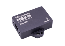
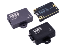
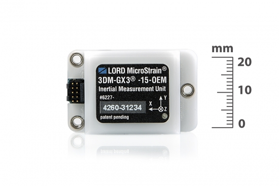
The 3DM-GX3® -15-OEM is a lower cost, miniature, industrial-grade inertial measurement unit (IMU) and vertical reference unit (VRU) in an OEM form factor.
Product Highlights
- High performance integrated MEMS sensor technology provide direct and computed IMU and VRU outputs in a small package.
- Triaxial accelerometer, gyroscope, and temperature sensors achieve the best combination of measurement qualities.
- On-board processor runs a sophisticated Complimentary Filter (CF) fusion algorithm for precise inclination estimates and inertial measurements
- Sampling rates up to 30 KHz and data output up to 1 KHz
- Small size, lightweight packaging, and header connector interface ideal for OEM integration
Product no longer stocked – limited availability
Contact for pricing and lead time--a minimum order quantity may apply
DatasheetThe 3DM-DH3 provides accurate drill path measurements including Inclination, Azimuth, GTF, MTF, Dip Angle, sensor temperatures, G-TOT and H-TOT.
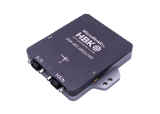
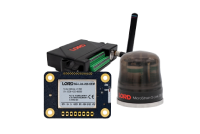
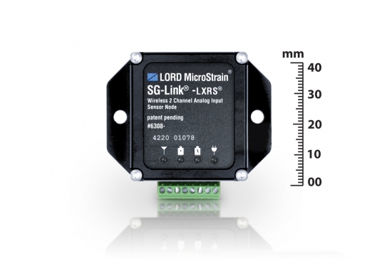
The SG-Link® -LXRS® is a small, low-power, two-channel analog input sensor node with many sampling options.
Product Highlights
- One differential and one single-ended analog input channel and an internal temperature sensor
- Ideal for remote and long term measurement of many Wheatstone bridge and analog-type sensors including: strain, force, torque, pressure, acceleration, vibration, magnetic field, displacement and geophones
- Supports continuous, burst, and event-triggered sampling and datalogging to internal memory
- User-programmable sample rates up to 4096 Hz
- IP65/66 environmental enclosures available
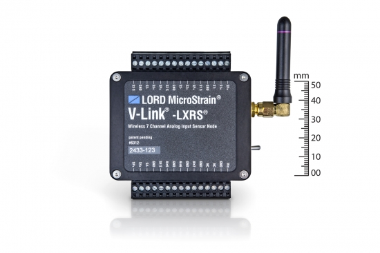
The V-Link® -LXRS® is a versatile seven channel analog wireless sensor node with high sample rates and datalogging capability.
Product Highlights
- Four differential and three single-ended analog input channels and an internal temperature sensor
- Ideal for remote and long term measurement of many Wheatstone bridge and analog-type sensors including: strain, force, torque, pressure, acceleration, vibration, magnetic field, displacement and geophones
- Supports continuous, burst, and event-triggered sampling and datalogging to internal memory
- l User-programmable sample rates up to 10 KHz
- l IP65/66 environmental enclosures available
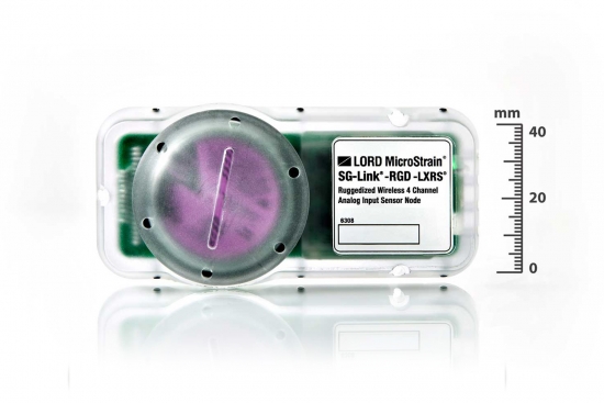
The SG-Link® -RGD -LXRS® ia a versatile, ruggedized four-channel analog sensor node with integrated triaxial accelerometer.
Product Highlights
- Four analog input channels, integrated three-axis accelerometer, and an internal temperature sensor
- Integrated strain sensor signal conditioning, embedded processing, and environmentally hardened form factor ideal for permanently mounting over strain gauges
- Supports conventional bonded foil, piezoelectric-resistive, Wheatstone bridge, and modular Columbia Research
- Labs-type strain gauges
- Integrated triaxial accelerometer with MEMS technology and +/- 16 g range
- User-programmable sample rates up to 4096 Hz
Best in Class Performance
- Fully calibrated, temperature compensated, and mathematically aligned to an orthogonal coordinate system for highly accurate outputs
- Bias tracking, error estimation, threshold flags, and adaptive noise modeling allow for fine tuning to conditions in each application.
Ease of Use
- Easy integration via comprehensive SDK
- Common protocol with the 3DM-GX4® and 3DM-RQ1™ sensor families for easy migration
Cost Effective
- Out-of-the box solution reduces development time.
- Volume discounts
Best in Class
- Precise downhole orientation
- High-speed sample rate & flexible data outputs
- Extended use, low-power data logging
Easiest to Use
- Rapid deployment in the drill string
- Outputs drill path measurements
Cost Effective
- Reduced cost and rapid time to market for customer’s applications
- Aggressive volume discount schedule
Wireless Simplicity, Hardwired Reliability
High Performance
- Scalable, long range wireless sensor networks up to 2 km
- Lossless data throughput under most operating conditions
Ease of Use
- Rapid deployment with wireless framework
- Low power consumption allows extended use.
- Remotely configure nodes, acquire and view sensor data with Node Commander®.
- Optional web-based SensorCloud™ interface optimizes data storage, viewing, and analysis.
- Easy integration via comprehensive SDK
Cost Effective
- Out-of-the box wireless sensing solution reduces development and deployment time.
- Volume discounts
Wireless Simplicity, Hardwired Reliability
High Performance
- Node-to-node synchronization up to ±32 microseconds
- High resolution data with 16-bit A/D converter
- Scalable, long range wireless sensor networks up to 2 km
- Lossless data throughput under most operating conditions
Ease of Use
- Rapid deployment with wireless framework
- Event driven triggers for efficient monitoring
- Remotely configure nodes, acquire and view sensor data with Node Commander®.
- Optional web-based SensorCloud™ interface optimizes data storage, viewing, and analysis.
- Easy integration via comprehensive SDK
Cost Effective
- Reduction of costs associated with wiring
- Low-cost per channel with 7 input channels per node
Wireless Simplicity, Hardwired Reliability
High Performance
- Node-to-node synchronization up to ±32 microseconds
- High resolution data with 16-bit A/D converter
- Scalable, long range wireless sensor networks up to 2 km
Ease of Use
- Flex bonding cable and node form factor allow quick installation over existing strain gauges
- Low profile, environmentally sealed enclosure
- On-board shunt calibration
Cost Effective
- Reduction of costs associated with wiring
- Out-of-the box wireless sensing solution reduces development and deployment time.
|
General |
|||
|---|---|---|---|
|
Integrated sensors |
Triaxial accelerometer, triaxial gyroscope, triaxial magnetometer, and temperature sensors, |
||
|
Data outputs |
Inertial Measurement Unit (IMU) outputs: acceleration, angular rate, magnetic field , deltaTheta, deltaVelocity Computed outputs: attitude estimates (in Euler angles, quaternion, orientation matrix), |
||
|
Resolution |
16 bit SAR oversampled to 17 bits |
||
|
Inertial Measurement Unit (IMU) Sensor Outputs |
|||
|
Accelerometer |
Gyroscope |
Magnetometer |
|
|
Measurement range |
±5 g (standard) ±1.7±16, and ±50 g (option) |
300°/sec (standard) ±50, ±600,±1200 °/sec (options) |
±2.5 Gauss |
|
Non-linearity |
±0.1 % fs |
±0.03 % fs |
±0.4 % fs |
|
Bias instability |
±0.04 mg |
18°/hr |
-- |
|
Initial bias error |
±0.002 g |
±0.25°/sec |
±0.003 Gauss |
|
Scale factor stability |
±0.05 % |
±0.05 % |
±0.1 % |
|
Noise density |
80 µg/√Hz |
0.03°/sec/√Hz |
100 µGauss/√Hz |
|
Alignment error |
±0.05° |
±0.05° |
±0.05° |
|
Adjustable bandwidth |
225 Hz (max) |
440 Hz (max) |
230 Hz (max) |
|
IMU filtering |
Digitally filtered (user adjustable) and scaled to physical input; coning and sculling integrals computed at 1 kHz |
||
|
Sampling rate |
30 kHz |
30 kHz |
7.5 kHz |
|
IMU data output rate |
1 Hz to 1000 Hz |
||
|
Computed Outputs |
|||
|
Attitude accuracy |
±0.5° roll, pitch, and heading (static, typ), ±2.0° roll, pitch, and heading (dynamic, typ) |
||
|
Attitude heading range |
360° about all axes |
||
|
Attitude resolution |
< 0.01° |
||
|
Attitude repeatability |
0.2° (typ) |
||
|
Calculation update rate |
1000 Hz |
||
|
Computed data output rate |
1 Hz to 500 Hz |
||
|
Operating Parameters |
|||
|
Communication |
USB 2.0, TTL (3.3 V dc, 9,600 bps to 921,600 bps, default 115,200) |
||
|
Power source |
+ 3.1 to + 5.5 V dc |
||
|
Power consumption |
80 mA at 5 V dc (USB) |
||
|
Operating temperature |
-40 °C to +70 °C |
||
|
Mechanical shock limit |
500 g |
||
|
Physical Specifications |
|||
|
Dimensions |
38 mm x 24 mm x 11.6 mm |
||
|
Weight |
11.6 grams |
||
|
Regulatory compliance |
ROHS |
||
|
Integration |
|||
|
Connectors |
Data/power output: Samtec FTSH Series (FTSH-105-01-F-D-K) |
||
|
Software |
MIP™ Monitor, Windows XP/Vista/7/8 compatible |
||
|
Compatibility |
Protocol compatibility with 3DM-RQ1™ and 3DM- GX4® sensor families. |
||
|
Software development kit (SDK) |
MIP™ data communications protocol with sample code available (OS and computing platform independent) |
||
|
General |
|||
|---|---|---|---|
|
Integrated sensors |
Triaxial accelerometer, triaxial gyroscope, and temperature sensors |
||
|
Data outputs |
Inertial Measurement Unit (IMU) outputs: acceleration, angular rate, deltaTheta, deltaVelocity Computed outputs: attitude estimates (Euler angles, quaternion, orientation matrix) |
||
|
Resolution |
16 bit SAR oversampled to 17 bits |
||
|
Inertial Measurement Unit (IMU) Sensor Outputs |
|||
|
Accelerometer |
Gyroscope |
||
|
Measurement range |
±5 g (standard) ±1.7, and ±50g. (option) |
300°/sec (standard) ±50, ±600, ±1200°/sec (options) |
|
|
Non-linearity |
±0.1 % fs |
±0.03 % fs |
|
|
Bias instability |
±0.04 mg |
18°/hr |
|
|
Initial bias error |
±0.002 g |
±0.25°/sec |
|
|
Scale factor stability |
±0.05 % |
±0.05 % |
|
|
Noise density |
80 µg/√Hz |
0.03°/sec/√Hz |
|
|
Alignment error |
±0.05° |
±0.05° |
|
|
Adjustable bandwidth |
225 Hz (max) |
440 Hz (max) |
|
|
IMU filtering |
Digitally filtered (user adjustable) and scaled to physical inputs; coning and sculling integrals computed at 1 kHz |
||
|
Sampling rate |
30 kHz |
30 kHz |
|
|
IMU data output rate |
1 Hz to 1000 Hz |
||
|
Computed Outputs |
|||
|
Roll and pitch accuracy |
±0.5° (static, typ), ±2.0° (dynamic, typ) |
||
|
Roll and pitch range |
360° about all axes |
||
|
Roll and pitch resolution |
< 0.01° |
||
|
Roll and pitch repeatability |
0.2° (typ) |
||
|
Calculation update rate |
1000 Hz |
||
|
Computed data output rate |
1 Hz to 500 Hz |
||
|
Operating Parameters |
|||
|
Communication |
USB 2.0, TTL serial UART (3.3 V dc, 9,600 bps to 921,600 bps, default 115,200) |
||
|
Power source |
+ 3.1 to + 5.5 V dc |
||
|
Power consumption |
80 mA at 5 V dc (USB) |
||
|
Operating temperature |
-40 °C to +70 °C |
||
|
Mechanical shock limit |
500 g |
||
|
Physical Specifications |
|||
|
Dimensions |
38 mm x 24 mm x 11.6 mm |
||
|
Weight |
11.6 grams |
||
|
Regulatory compliance |
ROHS |
||
|
Integration |
|||
|
Connectors |
Data/power output: Samtec FTSH Series (FTSH-105-01-F-D-K) |
||
|
Software |
MIP™ Monitor, Windows XP/Vista/7/8 compatible |
||
|
Compatibility |
Protocol compatibility with 3DM-RQ1™ and 3DM- GX4® sensor families. |
||
|
Software development kit (SDK) |
MIP™ data communications protocol with sample code available (OS and computing platform independent) |
||
Sensor
- A/D resolution 24 bits accelerometer; 16 bits magnetometer
- Angle resolution 0.02˚
- Accuracy ± 0.2˚ inclination ± 0.5˚ azimuth
- Angle measurement repeatability 0.1°
Operation
- Output data rates up to 8Hz
- Output inclination, azimuth, GTF, MTF, Dip Angle, G-TOT, H-TOT
- Datalogging capacity up to 32,768 data records
Package
- CNC Anodized Aluminum
- Precision alignment features
- Highly compact and low profile
- 177.0 mm x 21.0mm diameter
- 91.0 grams
- RS422
- –40 to +125 °C operating temperature range
|
General |
|
|---|---|
|
Sensor input channels |
Differential analog, 1 channel Single-ended analog, 1 channel |
|
Integrated sensors |
Internal temperature, 1 channel |
|
Data storage capacity |
2 M bytes (up to 1,000,000 data points, data type dependent) |
|
Analog Input Channels |
|
|
Measurement range |
Differential: full-bridge, ≥ 350 Ω (factory configurable) Single-ended: 0 to 3 V dc |
|
Accuracy |
± 0.1% full scale typical |
|
Resolution |
12 bit |
|
Anti-aliasing filter bandwidth |
Single-pole Butterworth -3 dB cutoff @ 250 Hz (factory configurable) |
|
Bridge excitation voltage |
+3 V dc, 50 mA total for all channels (pulsed @ sample rates ≤ 16 Hz to conserve power) |
|
Measurement gain and offset |
User-selectable in software on differential channels gain values from 104 to 1800 |
|
Integrated Temperature Channel |
|
|
Measurement range |
-40 °C to 85 °C |
|
Accuracy |
± 2 °C (at 25 °C) typical |
|
Resolution |
12 bit |
|
Sampling |
|
|
Sampling modes |
Synchronized, low duty cycle, datalogging |
|
Sampling rates |
Continuous sampling: 1 sample/hour to 512 Hz Periodic burst sampling: 32 Hz to 4096 Hz Datalogging: 32 Hz to 4096 Hz |
|
Sample rate stability |
± 3 ppm |
|
Network capacity |
Up to 2000 nodes per RF channel (and per gateway) depending on the number of active channels and sampling settings. Refer to the system bandwidth calculator: http://www.microstrain.com/configure-your-system |
|
Synchronization between nodes |
± 32 μsec |
|
Operating Parameters |
|
|
Radio frequency (RF) transceiver carrier |
2.405 to 2.470 GHz direct sequence spread spectrum over 14 channels, license free worldwide, radiated power programmable from 0 dBm (1 mW) to 16 dBm (39 mW); low power option available for use outside the U.S.- limited to 10dBm (10mW) |
|
Range for bi-directional RF link |
70 m to 2 km line of sight with RF power setting |
|
RF communication protocol |
IEEE 802.15.4 |
|
Power source |
Internal: 3.7 V dc, 250 mAh lithium ion rechargeable battery External: +3.2 to +9.0 V dc |
|
Power consumption |
See power profile : |
|
Operating temperature |
-20 ˚C to + 60 ˚C (extended temperature range available with custom battery/enclosure, -40 ˚C to + 85 ˚C electronics only) |
|
Acceleration limit |
500 g standard (high g option available) |
|
Physical Specifications |
|
|
Dimensions |
58 mm x 50 mm x 21 mm |
|
Weight |
42 grams |
|
Environmental rating |
Indoor use (IP65/66 enclosures available) |
|
Enclosure material |
ABS plastic |
|
Integration |
|
|
Compatible gateways |
All WSDA® base stations and gateways |
|
Compatible sensors |
Bridge type analog sensors, 0 to 3 V dc analog sensors |
|
Connectors |
Screw terminal block |
|
Shunt calibration |
Internal shunt calibration resistor 499 KΩ, differential channel |
|
Software |
SensorCloud™, SensorConnect™, Node Commander®, Windows 7 (or newer) |
|
Software development |
Open-source MicroStrain Communications Library (MSCL) with sample code available in C++,Python,and.NET formats (OS and computing platform independent): http://lord-microstrain.github.io/MSCL/ |
|
Regulatory compliance |
FCC (U.S.), IC (Canada), ROHS |
| General | |
|---|---|
|
Sensor input channels |
Differential analog, 4 channels Single-ended analog, 3 channels |
|
Integrated sensors |
Internal temperature, 1 channel |
|
Data storage capacity |
4 M bytes (up to 2,000,000 data points, data type dependent) |
| Analog Input Channels | |
|
Measurement range |
Differential: full-bridge, ≥ 350 Ω (factory configurable) Single-ended: 0 to 3 V dc |
|
Accuracy |
± 0.1% full scale typical |
|
Resolution |
16 bit |
|
Anti-aliasing filter bandwidth |
Single-pole Butterworth -3 dB cutoff @ 250 Hz (factory configurable) |
|
Bridge excitation voltage |
+3 V dc, 50 mA total for all channels (pulsed @ sample rates ≤ 16 Hz to conserve power) |
|
Measurement gain and offset |
User-selectable in software on differential channels gain values from 21 to 13074 |
| Integrated Temperature Channel | |
|
Measurement range |
-40 °C to 85 °C |
|
Accuracy |
± 2 °C (at 25 °C) typical |
|
Resolution |
16 bit |
| Sampling | |
|
Sampling modes |
Synchronized, low duty cycle, datalogging, event-triggered |
|
Sampling rates |
Continuous sampling: 1 sample/hour to 512 Hz Periodic burst sampling: 32 Hz to 10 KHz Datalogging: 32 Hz to 10 KHz |
|
Sample rate stability |
± 3 ppm |
|
Network capacity |
Up to 2000 nodes per RF channel (and per gateway) depending on the number of active channels and sampling settings. Refer to the system bandwidth calculator: http://www.microstrain.com/configure-your-system |
|
Synchronization between nodes |
± 32 μsec |
| Operating Parameters | |
|
Radio frequency (RF) transceiver carrier |
2.405 to 2.470 GHz direct sequence spread spectrum over 14 channels, license free worldwide, radiated power programmable from 0 dBm (1 mW) to 16 dBm (39 mW); low power option available for use outside the U.S.- limited to 10dBm (10mW) |
|
Range for bi-directional RF link |
Outdoor/line-of-sight: 2 km (ideal) *, 800 m (typical)** Indoor/obstructions: 50 m (typical)** |
|
RF communication protocol |
IEEE 802.15.4 |
|
Power source |
Internal: 3.7 V dc, 650 mAh lithium ion rechargeable battery External: +3.2 to +9.0 V dc |
|
Power consumption |
See power profile : |
|
Operating temperature |
-20 ˚C to + 60 ˚C (extended temperature range available with custom battery/enclosure, -40 ˚C to + 85 ˚C electronics only) |
|
Acceleration limit |
500 g standard (high g option available) |
| Physical Specifications | |
|
Dimensions |
74 mm x 79 mm x 21 mm |
|
Weight |
141 grams |
|
Environmental rating |
Indoor use (IP65/66 enclosures available) |
|
Enclosure material |
Anodized aluminum |
| Integration | |
|
Compatible gateways |
All WSDA® base stations and gateways |
|
Compatible sensors |
Bridge type analog sensors, 0 to 3 V dc analog sensors |
|
Connectors |
Screw terminal block |
|
Shunt calibration |
Internal shunt calibration resistor 499 KΩ, differential channels |
|
Software |
SensorCloud™, Node Commander®, Windows XP/Vista/7 |
|
Software development |
Open-source MicroStrain Communications Library (MSCL) with sample code available in C++,Python,and.NET formats (OS and computing platform independent): http://lord-microstrain.github.io/MSCL/ |
|
Regulatory compliance |
FCC (U.S.), IC (Canada), CE, ROHS |
*Measured with antennas elevated, no obstructions, and no RF interferers.
**Actual range varies depending on conditions such as obstructions, RF interference, antenna height, & antenna orientation.
| General | |
|---|---|
|
Sensor input channels |
Differential analog, 4 channels |
|
Integrated sensors |
Triaxial MEMS accelerometer, 3 channels Internal temperature, 1 channel |
|
Data storage capacity |
2 M bytes (up to 1,000,000 data points, data type dependent) |
| Analog Input Channels | |
|
Measurement range |
Differential: full-bridge, ≥ 350 Ω (factory configurable) |
|
Accuracy and resolution |
± 0.1% full scale typical, 16 bit resolution |
|
Anti-aliasing filter bandwidth |
Single-pole Butterworth -3 dB cutoff @ 250 Hz |
|
Bridge excitation voltage |
+2.7 V dc, 50 mA total for all channels (pulsed @ sample rates ≤ 16 Hz to conserve power) |
|
Measurement gain and offset |
User-selectable in software on differential channels gain values from 104 to 1800 |
| Integrated Accelerometer Channels | |
|
Measurement range |
± 16 g |
|
Accuracy and resolution |
± 4 mg, 13 bit resolution |
| Integrated Temperature Channel | |
|
Measurement range |
-40 °C to 85 °C |
|
Accuracy and resolution |
± 2 °C (at 25 °C) typical, 16 bit resolution |
| Sampling | |
|
Sampling modes |
Synchronized, low duty cycle, datalogging |
|
Sampling rates |
Continuous sampling: 1 sample/hour to 512 Hz Periodic burst sampling: 32 Hz to 4096 Hz Datalogging: 32 Hz to 4096 Hz |
|
Sample rate stability |
± 3 ppm |
|
Network capacity |
Up to 2000 nodes per RF channel (and per gateway) depending on the number of active channels and sampling settings. Refer to the system bandwidth calculator: http://www.microstrain.com/configure-your-system |
|
Synchronization between nodes |
± 32 μsec |
| Operating Parameters | |
|
Radio frequency (RF) transceiver carrier |
2.405 to 2.470 GHz direct sequence spread spectrum over 14 channels, license free worldwide, radiated power programmable from 0 dBm (1 mW) to 16 dBm (39 mW); low power option available for use outside the U.S.- limited to 10dBm (10mW) |
|
Range for bi-directional RF link |
70 m to 2 km line of sight with RF power setting |
|
RF communication protocol |
IEEE 802.15.4 |
|
Power source |
Replaceable 3.7 V dc, 1.7 Ah Tadiran TL-5935 1/6 D-cell battery |
|
Power consumption |
960 uA ( 3.46 mW) @ 3.6 V dc, 32 HZ, 3 ch, no duty cycling 10.6 mA (38.16 mW) @ 3.6 V dc, 256 Hz, 3 ch, no duty cycling 4.0 mA (14.4 mW) @ 3.6 V dc, 256 Hz, 1 ch, no duty cycling |
|
Operating temperature |
-40 ˚C to + 85 ˚C |
|
Acceleration limit |
500 g standard (high g option available) |
| Physical Specifications | |
|
Dimensions |
101 mm x 46 mm x 26 mm |
|
Weight |
150 g (including battery) |
|
EMI/EMC rating |
MIL-STD-461F |
|
Enclosure material |
Clear polycarbonate |
| Integration | |
|
Compatible gateways |
All WSDA® base stations and gateways |
|
Compatible sensors> |
Bridge type analog sensors |
|
Connectors |
Flex cable terminal/solder pads (flex cable included) |
|
Shunt calibration |
Internal shunt calibration resistor 499 KΩ, differential channels< |
|
Software< |
SensorCloud™, SensorConnect™, Node Commander®, Windows 7 (or newer) |
|
Software development |
Open-source MicroStrain Communications Library (MSCL) with sample code available in C++,Python,and.NET formats (OS and computing platform independent): http://lord-microstrain.github.io/MSCL/ |
|
Regulatory compliance |
FCC (U.S.), IC (Canada), ROHS |
General Documentation
- 3DM-GX3® -25 OEM Product Datasheet
- 3DM-GX3® -25 OEM Mounting and Connector Information
- 3DM-GX3® -25 MIP Quick Start Guide
- 3DM-GX3® -25 Single Byte Quick Start Guide
- MIP Hard and Soft Iron Calibration Quick Start Guide
- 3DM-GX3® -15,-25 MIP Data Communications Protocol
- 3DM-GX3-25 Single Byte Data Communications Protocol
- Dewesoft™ 3DM-GX3® -25 Single Byte Plugin Instructions
- 3DM-GX3® Data Communications Protocol Errata
- MIP Software Downloads
- Firmware Upgrades for 3DM-GX3®
- Inertial product comparison
Technical Notes
- 3DM-GX3® Importing Magnetic Vectors
- Extending the USB Cable
- Using an Hardware Datalogger with Inertial Sensors
- 3DM-GX3® Startup Settings
- Using Dataloggers with Inertial Sensors
- Phihong PSA05R-090 Power Supply
- 3DM-GX3® -25 Up and North Compensation
- Working with the 3DM-GX3® -25 Update Mode
- Using the 3DM-GX3® -25 Capture Gyro Bias Function
- 3DM-GX3® -25 Coning and Sculling
- Operating the 3DM-GX3® -25 Software on the Mac OS X
Mechanical Prints (Uncontrolled)
Video
General Documentation
- 3DM-GX3® -15-OEM Datasheet
- 3DM-GX3® -15 Quick Start Guide
- 3DM-GX3® -15,-25 MIP Data Communications Protocol
- 3DM-GX3® Data Communications Protocol Errata
- MIP Software Downloads
- Firmware Upgrades for 3DM-GX3®
- 3DM-GX3® -15 OEM Mounting and Connector Information
- Inertial product comparison
Technical Notes
- Extending the USB Cable
- Using an Hardware Datalogger with Inertial Sensors
- 3DM-GX3® Startup Settings
- Using Dataloggers with Inertial Sensors
- Phihong PSA05R-090 Power Supply
Mechanical Prints (Uncontrolled)
General Documentation
Technical Notes
General Documentation
- SG-Link®-LXRS® Product Datasheet
- SG-Link®-LXRS® Quick Start Guide
- SG-Link®-LXRS® User Manual
- Node Commander Wireless Sensing Software User Manual
- Wireless Products Comparison
Technical Notes
- Powering a Wireless Node with Sources Greater Than 9 Volts
- Measuring Voltages Above 3 Volts with SG-Link®-LXRS®
- Using a Load Cell with SG-Link®-LXRS®
- LXRS® Firmware Upgrades
- Control a Relay with a Wireless Node
- Measuring Small Current
- Outputting a 4 to 20 mA Current Loop
- Using Pressure Transducers
- Battery Use and Replacement
- SG-Link® 350 Ohm Tester Board
- SG-Link® 1000 Ohm Tester Board
- IP and NEMA Rated Enclosures for Wireless Nodes
- SG-Link®-LXRS™ Power Profile
- Wireless Sensor Node Power Profiles
- Using External Power With Wireless Sensor Nodes
- Using the DEMOD-DC® with V-Link®-LXRS® and SG-Link®-LXRS®
- Synchronized Sampling on Startup
- Differential Analog Input Frequency Response Testing
- Distance Measurement with an IR Sensor
- Using Differential Inputs for a RTD
Mechanical Drawings (uncontrolled)
- SG-Link®-LXRS® Dimensional Drawing
- 6309-3000 SG-Link-IP66-ENCL
- 6309-4000 SG-Link-IP66-XL-ENCL
- 6309-5000 SG-Link-IP65-XXL-ENCL
- 6309-3000 IP66/NEMA4X Enclosure for SG-Link®-LXRS®
- 6309-4000 IP66/NEMA4X Enclosure for SG-Link®-LXRS® (1 battery)
- 6309-5000 IP65/NEMA4X Enclosure for SG-Link®-LXRS® (3 batteries)
Videos
General Documentation
- V-Link®-LXRS® Product Manual
- V-Link®-LXRS® Product Datasheet
- V-Link®–LXRS® Quick Start Guide
- V-Link®-LXRS® Document of Conformity
- Node Commander Wireless Sensing Software User Manual
- Wireless Products Comparison
Technical Notes
- Powering a Wireless Node with Sources Greater Than 9 Volts
- High Cycle Vibration and Function Test
- Event Driven Sampling
- Measuring Voltages Above 3 Volts with V-Link®-LXRS®
- LXRS® Firmware Upgrades
- Using a 4 to 20 mA Pressure Transducer
- Control a Relay with a Wireless Node
- Measuring Small Current
- Measuring Small Voltages
- Outputting a 4 to 20 mA Current Loop
- Using Pressure Transducers
- Battery Use and Replacement
- V-Link®-LXRS® 350 Ohm Tester Board
- V-Link®-LXRS® 1000 Ohm Tester Board
- V-Link®-LXRS® Pin Assignments
- Using the 50g, 100g, 200g or 500g Triaxial Accelerometer Cube
- IP and NEMA Rated Enclosures for Wireless Nodes
- Calculating a Linear Slope with Microsoft Excel®
- Using a Load Cell with V-Link®-LXRS™ and SG-Link®-LXRS®
- V-Link®-LXRS® Power Profile
- Wireless Sensor Node Power Profiles
- Using External Power With Wireless Sensor Nodes
- Using the DEMOD-DC® with V-Link®-LXRS® and SG-Link®-LXRS®
- Synchronized Sampling on Startup
- Distance Measurement with an IR Sensor
- Using Differential Inputs for a RTD
Mechanical Drawings (Uncontrolled)
- V-Link®–LXRS® Dimensional Drawing
- 6313-3100 V-Link-IP66-XL-ENCL
- 6313-3100 IP66/NEMA4X Enclosure for V-Link®-LXRS® (2 batteries)
Videos
General Documentation
- SG-Link® -RGD -LXRS® Datasheet
- Node Commander Wireless Sensing Software User Manual
- Wireless Products Comparison
Mechanical Drawings (Uncontrolled)
- SG-Link® -RGD -LXRS® Mechanical Drawing
- SG-Link® -RGD -LXRS® Accelerometer Orientation
- SG-Link® -RGD -LXRS® Wiring Diagram
Technical Notes
Software
Software
- MIP Monitor Data Acquisition Software
- MIP Software Development C Code Sample for Windows and Linux Version 1.1
- MIP LabVIEW Sample Code
- SensorConnect Data Acquisition Software (beta)
Mechanical