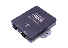
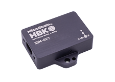
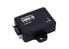
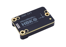
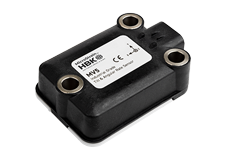
The FAS-A® Inclinometer is designed to provide 1 and 2-axis static and quasi-dynamic orientation measurements. It incorporates 3 accelerometers together with an on-board microprocessor, embedded software algorithm, non-volatile memory for configuration, and serial communication interface. Its form-factor, rated temperature range and power supply requirements are optimized for a broad array of applications. The FAS-A® outputs either one 360° roll axis or two +/-70° pitch and roll axes.
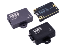
Datasheet ManualThe 3DM-GX3® -15 is a high-performance, miniature Inertial Measurement Unit and Vertical Gyro, utilizing MEMS sensor technology. It combines a triaxial accelerometer, triaxial gyro, temperature sensors, and an on-board processor running a sophisticated sensor fusion algorithm to provide static and dynamic orientation, and inertial measurements.
Datasheet Manual
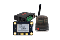
Inertia-Link® is a high-performance Inertial Measurement Unit and Vertical Gyro utilizing miniature MEMS sensor technology. It combines a triaxial accelerometer, triaxial gyro, temperature sensors, and an on-board processor running a sophisticated sensor fusion algorithm.
Inertia-Link® offers a range of output data quantities from fully calibrated inertial measurements (acceleration & angular rate or deltaAngle & deltaVelocity vectors) to computed orientation estimates (pitch & roll or rotation matrix). All quantities are fully temperature compensated and corrected for sensor misalignment. The angular rate quantities are further corrected for G-sensitivity and scale factor non-linearity to third order.
Inertia-Link's communications interface hardware is contained in a separable module, and can therefore be easily customized. Currently available interface modules include USB 2.0, RS232 and RS422. An OEM version is available without the communications interface enabling the sensor to be integrated directly into a host system's circuitboard, providing a very compact sensing solution.
The 3DM-GX2® Software Development Kit (SDK) provides application builders with robust protocols and source code samples to operate the Inertia-Link® and 3DM-GX2® orientation sensors. The SDK includes a complete Data Communications Protocol manual, a detailed Users manual, ANSI C Implementation and API. Sample applications demonstrating many protocol commands are provided with fully-commented source code for Microsoft® Visual Studio C++ 2003/2008 Express, LabVIEW® 7.1.1, Microsoft® Visual Studio Visual Basic 2005 and Microsoft® Visual Basic 6.0.
Product no longer stocked – limited availability
Contact for pricing and lead time--a minimum order quantity may apply
Datasheet Manual3DM-GX2® is a high-performance gyro enhanced orientation sensor which utilizes miniature MEMS sensor technology. It combines a triaxial accelerometer, triaxial gyro, triaxial magnetometer, temperature sensors, and an on-board processor running a sophisticated sensor fusion algorithm.
3DM-GX2® offers a range of output data quantities from fully calibrated inertial measurements (acceleration, angular rate and magnetic field or deltaAngle & deltaVelocity vectors) to computed orientation estimates (pitch & roll or rotation matrix). All quantities are fully temperature compensated and corrected for sensor misalignment. The angular rate quantities are further corrected for G-sensitivity and scale factor non-linearity to third order.
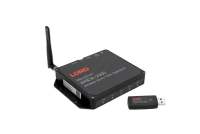
3DM-GX2®'s communications interface hardware is contained in a separable module, and can therefore be easily customized. Currently available interface modules include a wireless transceiver, USB 2.0, RS232 and RS422. An OEM version is available without the communications interface enabling the sensor to be integrated directly into a host system's circuitboard, providing a very compact sensing solution.
The system architecture has been carefully designed to substantially eliminate common sources of error such as hysteresis induced by temperature changes and sensitivity to supply voltage variations. The use of six independent Delta-Sigma A/D converters (one for each sensor) ensures that all sensors are sampled simultaneously, and that the best possible time integration results are achieved. On-board coning and sculling compensation allows for use of lower data output rates while maintaining performance of a fast internal sampling rate. 3DM-GX2® incorporates an integral triaxial magnetometer; optionally, the magnetometer can be located remotely to reduce hard and soft iron interference.
The 3DM-GX2® Software Development Kit (SDK) provides application builders with robust protocols and source code samples to operate the Inertia-Link® and 3DM-GX2® orientation sensors. The SDK includes a complete Data Communications Protocol manual, a detailed Users manual, ANSI C Implementation and API. Sample applications demonstrating many protocol commands are provided with fully-commented source code for Microsoft® Visual Studio C++ 2003/2008 Express, LabVIEW® 7.1.1, Microsoft® Visual Studio Visual Basic 2005 and Microsoft® Visual Basic 6.0.
Product no longer stocked – limited availability
Contact for pricing and lead time--a minimum order quantity may apply
Datasheet Manual
3DM-GX1® combines three angular rate gyros with three orthogonal DC accelerometers, three orthogonal magnetometers, multiplexer, 16 bit A/D converter, and embedded microcontroller, to output its orientation in dynamic and static environments.
Operating over the full 360 degrees of angular motion on all three axes, 3DM-GX1® provides orientation in matrix, quaternion and Euler formats. The digital serial output can also provide temperature compensated, calibrated data from all nine orthogonal sensors at update rates of 350 Hz.
Networks of 3DM-GX1® nodes can be deployed by using the built-in RS-485 network protocol. Embedded microcontrollers relieve the host system from the burden of orientation calculations, allowing deployment of dozens of 3DM-GX1® nodes with no significant decrease in system throughput.
Output modes and software filter parameters are user programmable. Programmed parameters and calibration data are stored in nonvolatile memory.
Product no longer stocked – limited availability
Contact for pricing and lead time--a minimum order quantity may apply
Datasheet ManualThe 3DM® Orientation Sensor is designed to provide 3-axis static and quasi-dynamic orientation measurements. It incorporates 3 accelerometers and 3 magnetometers together with an on-board microprocessor, embedded software algorithm, non-volatile memory for configuration, and serial communication interface. Its form-factor, rated temperature range and power supply requirements are optimized for a broad array of applications. The 3DM® outputs acceleration vectors, magnetic field vectors, Euler angles (pitch, roll, yaw) and orientation matrix.
Datasheet ManualThe 3DM-GX3® -25 is a high-performance, miniature Attitude Heading Reference System (AHRS), utilizing MEMS sensor technology. It combines a triaxial accelerometer, triaxial gyro, triaxial magnetometer, temperature sensors, and an on-board processor running a sophisticated sensor fusion algorithm to provide static and dynamic orientation, and inertial measurements.
Product no longer stocked – limited availability
Contact for pricing and lead time--a minimum order quantity may apply
Datasheet ManualThe 3DM-GX3® -45 high-performance, miniature GPS-Aided Inertial Navigation System (GPS/INS) combines MEMS inertial sensors, a highly-sensitive embedded GPS receiver, and a complex Extended Kalman Filter to generate optimal position, velocity, and attitude (PVA) estimates. This combination of technologies creates better short-term GPS-out performance, sustained-G attitude performance, and provides higher rate PVA data than typical GPS and AHRS sensors. Raw GPS data, IMU data, and filtered INS data are time-aligned and available as user-defined packets (either by polling or continuous stream).
Product no longer stocked – limited availability
Contact for pricing and lead time--a minimum order quantity may apply
Datasheet ManualBest in Class
- high-speed sample rate & flexible data outputs
- extended use, low-power data logging
Easiest to Use
- out-of-the-box pitch and roll
Cost Effective
- reduced cost and rapid time to market for customer’s applications
- aggressive volume discount schedule
Best in Class
- precise inertial measurements
- high-speed sample rate & flexible data outputs
- high performance under vibration and high g
Easiest to Use
- smallest, lightest industrial IMU available
- simple integration supported by SDK and comprehensive API
Cost Effective
- reduced cost and rapid time to market for customer’s applications
- aggressive volume discount schedule
- small, light-weight, low-power design ideal for size-sensitive applications including wearable devices
- fully temperature compensated over entire operational range
- calibrated for sensor misalignment, gyro G-sensitivity, and gyro scale factor non-linearity
- simultaneous sampling for improved time integration performance
- available with wireless and USB communication interfaces
- user adjustable data rate (1 to 250Hz) and sensor bandwith (1 to 100Hz)
- outputs include Euler angles, rotation matrix, deltaAngle & deltaVelocity, acceleration and angular rate vectors
- Small, light-weight, low-power design ideal for size-sensitive applications including wearable devices
- Fully temperature compensated over entire operational range
- Calibrated for sensor misalignment, gyro G-sensitivity, and gyro scale factor non-linearity
- Simultaneous sampling for improved time integration performance
- Available with wireless and USB communication interfaces
- User adjustable data rate (1 to 256Hz) and sensor bandwidth(1 to 100Hz)
- Outputs include Euler angles, rotation matrix, deltaAngle & deltaVelocity, acceleration and angular rate vectors
- On-board processing/filtering of accelerometer, gyro and magnetometer outputs
- Fully temperature compensated
- Calibrated for sensor misalignment and gyro G-sensitivity
- Supports hard iron field calibration
- Outputs Euler angles, quaternions and orientation matrix
- RS-232, RS-485 and analog output options
- Small, lightweight and low power
Best in Class
- high-speed sample rate & flexible data outputs
- extended use, low-power data logging
Easiest to Use
- out-of-the-box pitch, roll, and yaw
Cost Effective
- reduced cost and rapid time to market for customer’s applications
- aggressive volume discount schedule
Best in Class
- precise attitude estimations
- high-speed sample rate & flexible data outputs
- high performance under vibration and high g
Easiest to Use
- smallest, lightest industrial AHRS available
- simple integration supported by SDK and comprehensive API
Cost Effective
- reduced cost and rapid time to market for customer’s applications
- aggressive volume discount schedule
Best in Class
- precise position, velocity and attitude estimations
- high-speed sample rate & flexible data outputs
- high performance under vibration and high-g
Easiest to Use
- smallest, lightest industrial GPS/INS available
- simple integration supported by SDK and comprehensive API
Cost Effective
- reduced cost and rapid time to market for customer’s applications
- aggressive volume discount schedule
Product no longer stocked – limited availability Contact for pricing and lead time--a minimum order quantity may apply
|
Application |
static/quasi-dynamic measurements |
|
Sensor suite |
accelerometers |
|
Orientation range |
360° in single axis mode; +/-70° in dual axis mode |
|
Accelerometer range |
+/-1.7g |
|
Accelerometer bias stability |
0.003g |
|
Accelerometer nonlinearity |
0.2% |
|
A/D resolution |
12 bits |
|
Orientation accuracy |
+/-0.7° typical |
|
Orientation resolution |
<0.1° at most aggressive setting |
|
Repeatability |
pitch and roll 0.7° typical |
|
Output modes |
pitch and roll |
|
Analog output |
included cable provides voltage linearly proportional to inclination; 0-4.096 volts full scale |
|
Communication interface |
RS-232 |
|
Communication/power connector |
8 pin DIN type |
|
Data rate |
40 Hz |
|
Filtering |
infinite impulse response (IIR); user programmable weighted moving average |
|
Baud rate |
9600 |
|
Power supply voltage |
+5.2 to +12.0 VDC |
|
Power consumption |
40 mA |
|
Operating temperature |
-25°C to +70°C |
|
Dimensions |
64mm x 89mm x 25mm |
|
Weight |
62 grams |
|
Shock limit |
500g |
|
Software |
XP/Vista/Win7 |
IMU Specifications
|
Attitude and Heading |
|
|
Attitude heading range |
360° about all 3 axes |
|
Accelerometer range |
±5 g standard |
|
Gyroscope range |
±300°/sec standard |
|
Static accuracy |
±0.5° pitch and roll typical for static test conditions |
|
Dynamic accuracy |
±2.0° pitch and roll for dynamic (cyclic) test conditions and for arbitrary angles |
|
Long term drift |
pitch and roll drift eliminated by complementary filter architecture |
|
Repeatability |
0.2° |
|
Resolution |
<0.1° |
|
Data output rate |
up to 1000 Hz |
|
Filtering |
sensors sampled at 30 kHz, digitally filtered (user adjustable ) and scaled into physical units; coning and sculling integrals computed at 1 kHz |
|
Output modes |
acceleration, angular rate, deltaTheta, deltaVelocity, Euler angles, quaternion, rotation matrix |
| General | |
|
A/D resolution |
16 bits SAR oversampled to 17 bits |
|
Interface options |
USB 2.0 or RS232 |
|
Baud rate |
115,200 bps to 921,600 bps |
|
Power supply voltage |
+3.2 to +16 volts DC |
|
Power consumption |
80 mA @ 5 volts with USB |
|
Connector |
micro-DB9 |
|
Operating temperature |
-40° C to +70° C |
|
Dimensions |
44 mm x 24 mm x 11 mm - excluding mounting tabs, width across tabs 37 mm |
|
Weight |
18 grams |
|
ROHS |
compliant |
|
Shock limit |
500 g |
|
Software utility |
CD in starter kit (XP/Vista/Win7/Win8 compatible) |
|
Software development kit (SDK) |
complete data communications protocol and sample code |
Sensor Specifications
|
Accels |
Gyros |
|
|
Measurement range |
±5 g |
±300°/sec |
|
Non-linearity |
±0.1 % fs |
±0.03 % fs |
|
In-run bias stability |
±0.04 mg |
18°/hr |
|
Initial bias error |
±0.002 g |
±0.25°/sec |
|
Scale factor stability |
±0.05 % |
±0.05 % |
|
Noise density |
80 µg/√Hz |
0.03°/sec/√Hz |
|
Alignment error |
±0.05° |
±0.05° |
|
User adjustable bandwidth |
225 Hz max |
440 Hz max |
|
Sampling rate |
30 kHz |
30 kHz |
|
Options |
||
|
Accelerometer range |
±1.7 g, ±16 g, ±50 g |
|
|
Gyroscope range |
±50°/sec, ±600°/sec, ±1200°/sec |
|
| Orientation Range (pitch, roll, yaw) | 360˚ about all axes |
| Accelerometer range | +/- 5 g standard +/- 1.7 g and +/- 18 g also available (+/- 18 g may require export license) |
| Accelerometer bias stability | ± 0.010 g for ± 18 g range ± 0.005 g for ± 5 g range ± 0.003 g for ± 1.7 g range |
| Accelerometer nonlinearity | 0.2% |
| Gyro range | Gyros: ± 300°/sec standard, ± 1200°/sec, ± 600°/ sec, ± 50°/sec also available |
| Gyro bias stability | ± 0.2˚/sec for ± 300˚/sec |
| RF Output Power | 0dBm (1 mW) |
| Gyro nonlinearity | 0.2% |
| A/D resolution | 16 bits |
| Orientation Accuracy | ± 0.5˚ typical for static test conditions ± 2.0˚ typical for dynamic (cyclic) test conditions and for arbitrary orientation angles |
| Orientation Resolution | <0.1˚ minimum |
| Repeatability | 0.20˚ |
| Output modes | Acceleration and angular rate, deltaAngle and deltaVelocity, Euler angles, rotation matrix |
| Interface options | RS232, RS422, USB 2.0 and wireless - 2.45 GHz IEEE 802.15.4 direct sequence spread spectrum, license free worldwide (2.450 to 2.490 GHz) - 16 channels |
| Wireless communication range | 70 m |
| Digital output rates | Standard RS-232, USB or RS-422 interface: Up to 237Hz Wireless interface: Up to 100Hz OEM or custom interface: Up to 1000Hz |
| Serial data rate | 115200 bps |
| Supply voltage | +4.5 to +16 volts DC |
| Power consumption | 90 mA |
| Connectors | micro DB9 |
| Operating temperature | -40 to +70˚C with enclosure -40 to +85˚C without enclosure |
| Dimensions | 41 mm x 63 mm x 24 mm with enclosure 32 mm x 36 mm x 15 mm without enclosure |
| Weight | 39 grams with enclosure, 16 grams without enclosure |
| Shock limit | 1000 g (unpowered), 500 g (powered) |
*Accuracy and stability specifications obtained over operating temperatures of -40 to 70˚C with known sine and step inputs, including angular rates of ± 300˚ per second.
Patents pending.
| Orientation Range (pitch, roll, yaw) |
360° about all axes |
| Accelerometer range | +/- 5 g standard +/- 1.7 g and +/- 18 g also available (+/- 18 g may require export license) |
| Accelerometer bias stability | ± 0.010 g for ± 18 g range ± 0.005 g for ± 5 g range ± 0.003 g for ± 1.7 g range |
| Accelerometer Nonlinearity | 0.2% |
| Gyro range | Gyros: ± 300°/sec standard, ± 1200°/sec, ± 600°/ sec, ± 50°/sec also available |
| Gyro Bias Stability | ± 0.2°/sec for ± 300°/sec |
| Gyro nonlinearity | 0.2% |
| Magnetometer range | ± 1.2 Gauss |
| Magnetometer nonlinearity | 0.4% |
| Magnetometer bias stability | 0.01 Gauss |
| A/D resolution | 16 bits |
| Orientation Accuracy | ± 0.5° typical for static test conditions ± 2.0° typical for dynamic (cyclic) test conditions & for arbitrary orientation angles |
| Orientation resolution | <0.1° minimum |
| Repeatability | 0.20° |
| Output modes | Acceleration and angular rate, deltaAngle and deltaVelocity, Euler angles, rotation matrix |
| Interface options | RS232, RS422, USB 2.0 and wireless - 2.45 GHz IEEE 802.15.4 direct sequence spread spectrum, license free worldwide (2.450 to 2.490 GHz) - 16 channels |
| Wireless communication range | 70 m |
| Digital output rates | Standard RS-232, USB or RS-422 interface: Up to 237Hz Wireless interface: Up to 100Hz OEM or custom interface: Up to 1000Hz |
| Serial data rate | 115200 bps |
| Supply voltage | +4.5 to 16 volts |
| Power consumption | 90 mA |
| Connectors | micro DB9 |
| Operating temp. | -40 to +70°C with enclosure -40 to +85°C without enclosure |
| Dimensions | 41 mm x 63 mm x 32 mm with enclosure 32 mm x 36 mm x 24 mm without enclosure |
| Weight | 50 grams with enclosure, 21 grams without enclosure |
| Shock limit | 1000 g (unpowered), 500g (powered) |
| RF Output Power | 0dBm (1 mW) |
U.S. Patents Pending
| Orientation Range | 360˚ full scale (FS), all axes (Matrix, Quaternion modes) |
| Accelerometer range | +/- 5 g standard +/- 1.7 g and +/- 18 g also available (+/- 18 g may require export license) |
| Accelerometer bias stability | +/- 0.005 g for +/- 5 g range +/- 0.003 g for +/- 1.7 g range +/- 0.010 g for +/- 18 g range |
| Accelerometer Nonlinearity | 0.2% |
| Gyro range | +/- 300°/sec standard +/- 1200°/sec, +/- 600°/sec, +/- 50°/sec also available |
| Gyro Nonlinearity | 0.2% |
| Gyro Bias Stability* | 0.7˚/sec |
| Magnetometer Nonlinearity | 0.4% |
| Magnetometer Bias Stability* | .010 Gauss |
| Orientation Resolution | < 0.1˚ minimum |
| Repeatability | 0.20˚ |
| A/D Resolution | 16 bits |
| Accuracy | ±0.5˚ typical for static test conditions, ±2˚ typical for dynamic (cyclic) test conditions and for arbitrary orientation angles |
| Output Modes | Matrix, Quaternion, Euler angles and 9 scaled sensors with temperature |
| Digital Outputs | Serial RS-232 and RS-485 optional with software programming |
| Analog Output Option | 0-5 volts FS for Euler angles (pitch ±90, roll ±180, yaw 360˚) |
| Digital Output Rates | 100 Hz for Euler, Matrix, Quaternion; 350 Hz for nine orthogonal sensors only |
| Serial Data Rate | 19.2/38.4/115.2 Kbaud, software programmable |
| Supply Voltage | 5.2 VDC min., 12 VDC max. |
| Supply Current | 65 milliamps |
| Connectors | One keyed LEMO, two for RS-485 option |
| Operating Temperature | -40˚ to +70˚ C with enclosure; -40˚ to +85˚ C without enclosure |
| Enclosure (w/tabs) | 64 mm x 90 mm x 25 mm |
| Weight | 74.6 gr. with enclosure, 25.8 gr. without enclosure |
| Shock Limit | 1000 G's (unpowered); 500 G's (powered) |
*Accuracy and stability specifications obtained over operating temperatures of -40˚ to +70˚ C with known sine and step inputs, including angular rates of ± 300 degrees per second.
|
Application |
static/quasi-dynamic measurements |
|
Sensor suite |
accelerometers, magnetometers |
|
Orientation range |
360° about all axes |
|
Accelerometer range |
+/-1.7g |
|
Accelerometer bias stability |
0.003g |
|
Accelerometer nonlinearity |
0.2% |
|
Magnetometer range |
+/-6 Gauss |
|
Magnetometer bias stability |
0.4 Gauss |
|
Magnetometer nonlinearity |
0.85% |
|
A/D resolution |
12 bits |
|
Orientation accuracy |
pitch +/-0.7° typical, roll +/-0.7° typical, yaw +/-1.5° typical |
|
Orientation resolution |
<0.1° at most aggressive setting |
|
Repeatability |
pitch and roll 0.7° typical, yaw 0.26° typical |
|
Output modes |
acceleration, magnetic fields, Euler angles (pitch, roll, yaw), orientation matrix |
|
Communication interface |
RS-232 |
|
Communication/power connector |
RJ11 type |
|
Data rate |
angle mode up to 45 Hz; sensor mode up to 70 Hz |
|
Filtering |
infinite impulse response (IIR); user programmable weighted moving average |
|
Baud rate |
1200, 9600, 19200 |
|
Power supply voltage |
+5.2 to +12.0 VDC |
|
Power consumption |
50 mA |
|
Operating temperature |
-25°C to +70°C |
|
Dimensions |
64mm x 89mm x 25mm |
|
Weight |
62 grams |
|
Shock limit |
500g |
|
Software |
XP/Vista/Win7 |
AHRS Specifications
|
Attitude and Heading |
|
|
Attitude heading range |
360° about all 3 axes |
|
Accelerometer range |
±5g standard |
|
Gyroscope range |
±300°/sec standard |
|
Static accuracy |
±0.5° pitch, roll, heading typical for static test conditions |
|
Dynamic accuracy |
±2.0° pitch, roll, heading for dynamic (cyclic) test conditions and for arbitrary angles |
|
Long term drift |
eliminated by complimentary filter architecture |
|
Repeatability |
0.2° |
|
Resolution |
<0.1° |
|
Data output rate |
up to 1000 Hz |
|
Filtering |
sensors sampled at 30 kHz, digitally filtered (user adjustable ) and scaled into physical units; coning and sculling integrals computed at 1 kHz |
|
Output modes |
acceleration, angular rate, and magnetic field deltaTheta, deltaVelocity, Euler angles, quaternion, rotation matrix |
|
General |
|
|
A/D resolution |
16 bits SAR oversampled to 17 bits |
|
Interface options |
USB 2.0 or RS232 |
|
Baud rate |
115,200 bps to 921,600 bps |
|
Power supply voltage |
+3.2 to +16 volts DC |
|
Power consumption |
80 mA @ 5 volts with USB |
|
Connector |
micro-DB9 |
|
Operating temperature |
-40° C to +70° C |
|
Dimensions |
44 mm x 24 mm x 11 mm - excluding mounting tabs, width across tabs 37 mm |
|
Weight |
18 grams |
|
ROHS |
compliant |
|
Shock limit |
500 g |
|
Software utility |
CD in starter kit (XP/Vista/Win7/Win 8 compatible) |
|
Software development kit (SDK) |
complete data communications protocol and sample code |
Sensor Specifications
|
Accels |
Gyros |
Mags |
|
|
Measurement range |
±5 g |
±300°/sec |
±2.5 Gauss |
|
Non-linearity |
±0.1 % fs |
±0.03 % fs |
±0.4 % fs |
|
In-run bias stability |
±0.04 mg |
18°/hr |
— |
|
Initial bias error |
±0.002 g |
±0.25°/sec |
±0.003 Gauss |
|
Scale factor stability |
±0.05 % |
±0.05 % |
±0.1 % |
|
Noise density |
80 µg/√Hz |
0.03°/sec/√Hz |
100 µGauss/√Hz |
|
Alignment error |
±0.05° |
±0.05° |
±0.05° |
|
User adjustable bandwidth |
225 Hz max |
440 Hz max |
230 Hz max |
|
Sampling rate |
30 kHz |
30 kHz |
7.5 kHz max |
|
Options |
|||
|
Accelerometer range |
±1.7 g, ±16 g, ±50 g |
||
|
Gyroscope range |
±50°/sec, ±600°/sec, ±1200°/sec |
||
Navigation Specifications
|
Kalman Filter Performance |
|
|
Typical position accuracy † |
±2.5 m RMS horizontal, ±5 m RMS vertical |
|
Typical velocity accuracy † |
±0.1 m/s to ±0.75 m/s RMS (application and settings dependent) |
|
Typical attitude accuracy † |
±0.35 deg RMS roll & pitch ±1.0 deg RMS heading |
|
Update rate |
100 Hz |
|
Features |
|
|
Data output rate |
up to 1000 Hz |
AHRS Specifications
|
Attitude and Heading |
|
|
Attitude heading range |
360° about all 3 axes |
|
Accelerometer range |
±5g standard |
|
Gyroscope range |
±300°/sec standard |
|
Static accuracy |
±0.5° pitch, roll, heading typical for static test conditions |
|
Dynamic accuracy |
±2.0° pitch, roll, heading for dynamic (cyclic) test conditions and for arbitrary angles |
|
Long term drift |
eliminated by complimentary filter architecture |
|
Repeatability |
0.2° |
|
Resolution |
<0.1° |
|
Data output rate |
1 Hz to 100 Hz |
|
Filtering |
sensors sampled at 30 kHz, digitally filtered (user adjustable ) and scaled into physical units; coning and sculling integrals computed at 1 kHz |
|
Output modes |
acceleration, angular rate, magnetic field, deltaTheta, deltaVelocity, Euler angles, orientation matrix, quaternion, LLH position, NED velocity, GPS time, filter status, PVA estimate, PVA uncertainties, attitude as: quaternion, matrix, or Euler angles, gravity-free linear acceleration, bias-compensated angular rate |
|
General |
|
|
A/D resolution |
16 bits SAR oversampled to 17 bits |
|
Interface options |
USB 2.0 or RS232 |
|
Baud rate |
9,600 bps to 921,600 bps |
|
Power supply voltage |
+3.2 to +16 volts DC |
|
Power consumption |
at full performance with GPS lock: |
|
Connector |
micro-DB9 |
|
Operating temperature |
-40 °C to +65 °C |
|
Dimensions |
44 mm x 24 mm x 14 mm - excluding mounting tabs, width across tabs 37 mm |
|
Weight |
23 grams |
|
ROHS |
compliant |
|
Shock limit |
500 g |
|
Software utility |
CD in starter kit (XP/Vista/Win7/Win 8 compatible) |
|
Software development kit (SDK) |
complete data communications protocol and sample code |
| CE | compliant |
Sensor Specifications
|
Accels |
Gyros |
Mags |
|
|
Measurement range |
±5 g |
±300°/sec |
±2.5 Gauss |
|
Non-linearity |
±0.1 % fs |
±0.03 % fs |
±0.4 % fs |
|
In-run bias stability |
±0.04 mg |
18°/hr |
— |
|
Initial bias error |
±0.002 g |
±0.25°/sec |
±0.003 Gauss |
|
Scale factor stability |
±0.05 % |
±0.05 % |
±0.1 % |
|
Noise density |
80 µg/√Hz |
0.03°/sec/√Hz |
100 µGauss/√Hz |
|
Alignment error |
±0.05° |
±0.05° |
±0.05° |
|
User adjustable bandwidth |
225 Hz max |
440 Hz max |
230 Hz max |
|
Sampling rate |
30 kHz |
30 kHz |
7.5 kHz max |
GPS Specifications
|
GPS Receiver |
|
|
GPS receiver type |
50-channel u-blox 6 engine GPS L1 C/A code SBAS: WAAS, EGNOS, MSAS |
|
Data output rate |
1 Hz to 4 Hz |
|
Time-to-First-Fix |
Cold starts: 27 sec Aided starts: 4 sec Hot starts: 1 sec |
|
GPS tacking and navigation sensitivity |
-159 dBm |
|
Sensitivity |
Tracking: -159 dBm Cold starts: -147 dBm Hot starts: -158 dBm |
|
GPS velocity accuracy |
0.1 m/sec |
|
GPS heading accuracy |
0.5° |
|
GPS horizontal position accuracy |
position: 2.5 m CEP SBAS: 2.0 m CEP |
|
GPS timepulse signal accuracy |
30 nsec RMS < 60 nsec 99% |
|
GPS acceleration limit |
≤ 4 g |
|
GPS altitude limit |
no limit |
|
GPS velocity limit |
500 m/sec (972 knots) |
|
GPS antenna connector |
MMCX type |
|
Options |
|
|
Accelerometer range |
±1.7 g, ±16 g, ±50 g |
|
Gyroscope range |
±50°/sec, ±600°/sec, ±1200°/sec |
† RMS values generated from actual vehicle testing (airborne & land) when compared to a reference navigation unit
General Documentation
- FAS-A® Datasheet
- FAS-A® Data Communications Protocol
- FAS-A® Software Manual
- 8200-0008 (SOFTWARE, FAS-A)
Mechanical Prints
Software
General Documentation
- 3DM-GX3® -15 Datasheet
- 3DM-GX3® -15 Quick Start Guide
- 3DM-GX3® -15,-25 MIP Data Communications Protocol
- 3DM-GX3® Data Communications Protocol Errata
- 3DM-GX3® -15 Declaration of Conformity
Technical Notes
- Extending the USB Cable
- Using an Hardware Datalogger with Inertial Sensors
- 3DM-GX3® Startup Settings
- Using Dataloggers with Inertial Sensors
- Phihong PSA05R-090 Power Supply
- 3DM-GX3® -15 Communication and Power Connector
Mechanical Prints
- 3DM-GX3® -15 STP file
- 3DM-GX3® -15 Mounting Diagram
- 6212-1000 4005-0037 Micro D-to-RS232 Communication and Power Cable
- 6224-0100 Craft Cable with Micro DB9 and 9 flying leads
- 6212-1040 9022-0019 Micro D-to-USB Communication and Power Cable
Firmware Upgrade
Software Download
Software Development Kit
This product is now a legacy product.
General Documentation
- 3DM-GX1® Product Datasheet
- 3DM-GX1® Software Manual
- 3DM-GX1® Detailed Specifications
- 3DM-GX1® Comparison With and Without Temperature Compensation
- 3DM-GX1® Data Communication Protocol 3.1.02
- 8200-0007 (SOFTWARE, 3DM-GX1)
Mechanical Prints
- 3DM-GX1® 4-lead Analog Cable
- 3DM-GX1 Top Board Dimensions
- 3DM-GX1® PCB Assembly Dimensions
- 3DM-GX1® Enclosure print
- 3DM-GX1® RS-232 Communication/Power Cable
- 3DM-GX1® RS-485 Communication/Power Cable
- 3DM-GX1® Internal Wiring Block
Technical Notes
- Bluetooth and 3DM-GX1®
- RS-485 Addressing Limitations
- 3DM-GX1® Analog Output Option
- Orientation conversion formulas
- 3DM-GX1® Hard Iron Calibration
- 3DM-GX1® Timer Ticks, Calculation Cycle and Data Output Rates
- 3DM-GX1® Fastest Data Output Rates
- Using the 3DM-GX1® with the V-Link®
- 8200-0007 (SOFTWARE, 3DM-GX1)
Code Samples
- Sample Code including C, VB, Labview
- Certified LabView Plug and Play (project-style) Instrument Driver
- Sample C Code Showing Euler Angles
- Sample Linux Code
FAQ's
General Documentation
Mechanical Prints
- 3DM® Orientation, Case Dimensions and Wiring Connector
- 3DM® PCB Dimensions
- 3DM® Communication/Power Cable
Technical Notes
Software
General Documentation
- 3DM-GX3® -25 Product Datasheet
- 3DM-GX3® -25 MIP Quick Start Guide
- 3DM-GX3® -25 Single Byte Quick Start Guide
- MIP Hard and Soft Iron Calibration Quick Start Guide
- Single Byte Hard and Soft Iron Calibration Quick Start Guide
- 3DM-GX3® -15,-25 MIP Data Communications Protocol
- 3DM-GX3-25 Single Byte Data Communications Protocol
- 3DM-GX3® Data Communications Protocol Errata
- 3DM-GX3® -25 Declaration of Conformity
- 8200-0012 (SOFTWARE, 3DM-GX3-25 Single Byte firmware 1.XXX)
Technical Notes
- 3DM-GX3® Importing Magnetic Vectors
- Extending the USB Cable
- Using an Hardware Datalogger with Inertial Sensors
- 3DM-GX3® Startup Settings
- Using Dataloggers with Inertial Sensors
- Phihong PSA05R-090 Power Supply
- 3DM-GX3® -25 Up and North Compensation
- Working with the 3DM-GX3® -25 Update Mode
- Using the 3DM-GX3® -25 Capture Gyro Bias Function
- 3DM-GX3® -25 Communication and Power Connector
- 3DM-GX3® -25 Coning and Sculling
- Operating the 3DM-GX3® -25 Software on the Mac OS X
- Using the 3DM-GX3® -25 with Bluetooth® RS-232 Adapters
Mechanical Prints (Uncontrolled)
- 3DM-GX3® -25 STP file
- 3DM-GX3® -25/35/45 Mounting Holes
- 3DM-GX3® -25 Dimensional Drawing
- 3DM-GX3® -25 Mounting Diagram
- 6212-1000 4005-0037 Micro D-to-RS232 Communication and Power Cable
- 6224-0100 Craft Cable with Micro DB9 and 9 flying leads
- 6212-1040 9022-0019 Micro D-to-USB Communication and Power Cable
FAQs
Video
- Hard & Soft Iron Calibration
- Enabling Robotic Attitude Sensing and Autonomous Navigation Through Inertial Sensor Technology
Firmware Upgrade
Software Download
Software Development Kit
General Documentation
- 3DM-GX3® -45 Product Datasheet
- 3DM-GX3® -45 Theory of Operation
- 3DM-GX3® -45 Quick Start Guide
- MIP Hard and Soft Iron Calibration Quick Start Guide
- 3DM-GX3®-45 MIP Data Communications Protocol
- 3DM-GX3® Data Communications Protocol Errata
- 3DM-GX3® -45 Declaration of Conformity
Technical Notes
- 3DM-GX3® Importing Magnetic Vectors
- Selecting a Gyroscope Option
- Extending the USB Cable
- Using an Hardware Datalogger with Inertial Sensors
- 3DM-GX3® Startup Settings
- Using Dataloggers with Inertial Sensors
- Using u-blox Software with 3DM-GX3®-35 and 3DM-GX3®-45
- Outputting NMEA Packets to GPS Ready Software
- Using the 3DM-GX3® -45 with Bluetooth™ RS-232 Adapters
- Phihong PSA05R-090 Power Supply
- GPS Antenna Performance Comparison
- 3DM-GX3® -45 Firmware Errata
- 3DM-GX3® -45 Communication and Power Connector
Mechanical Prints (Uncontrolled)
- 3DM-GX3® -45 Mounting Diagram
- 3DM-GX3® GPS Antenna
- Gilsson Antenna Mounting
- 3DM-GX3® -45 STP file
- 3DM-GX3®-25/35/45 Mounting Holes
- 6224-0100 Craft Cable with Micro DB9 and 9 flying leads
- 3065-7046 3DM-GX3-45® Enclosure Lid Drawing
- 3065-7045 3DM-GX3-45® Enclosure Base Drawing
- 6225-4220 3DM-GX3-45® Dimensional Drawing
- 6212-1040 9022-0019 Micro D-to-USB Communication and Power Cable
- 6212-1000 4005-0037 Micro D-to-RS232 Communication and Power Cable
FAQ's
Video
- 3DM-GX3-45® Flight Test
- Hard & Soft Iron Calibration
- Enabling Robotic Attitude Sensing and Autonomous Navigation Through Inertial Sensor Technology
Firmware Upgrade
Software Download
Software Development Kit
