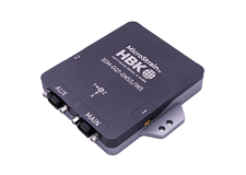
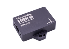
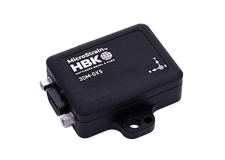
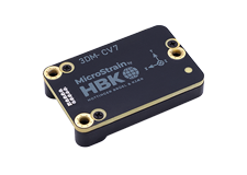
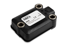
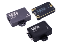
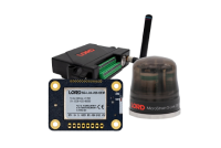
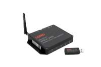
The CX product line has all the same features of the GX series in a cost-effective system-integrator friendly package designed for volume production.
The 3DMCV5-AHRS is a value focused AHRS designed to balance cost and performance.
The 3DM-GX3® -25-OEM is a lower cost, miniature, industrial-grade attitude heading and reference system (AHRS) with integrated magnetometers, and OEM form factor.
Product Highlights
- High performance integrated MEMS sensor technology provide direct and computed AHRS outputs in a small package.
- Triaxial accelerometer, gyroscope, magnetometer, and temperature sensors achieve the best combination of measurement qualities.
- On-board processor runs a sophisticated Complimentary Filter (CF) fusion algorithm for precise attitude estimates and inertial measurements
- Sampling rates up to 30 KHz and data output up to 1 KHz
- Small size, lightweight packaging, and header connector interface ideal for OEM integration
The 3DM-GX3® -35 is a miniature industrial-grade all-in-one navigation solution with integrated GPS and magnetometers, high noise immunity, and exceptional performance.
Product Highlights
- High performance integrated GPS receiver and MEMS sensor technology provide direct and computed PVA outputs in a small package.
- Triaxial accelerometer, gyroscope, magnetometer, temperature sensors, and a pressure altimeter achieve the best combination of measurement qualities.
- Dual on-board processors run a sophisticated Extended Kalman Filter (EKF) for excellent position, velocity, and attitude estimates.
The 3DM-GX4 -25™ is a miniature industrial-grade attitude heading and reference system (AHRS) with integrated magnetometers, high noise immunity, and exceptional performance.
Product Highlights
- High performance integrated MEMS sensor technologyprovide direct and computed AHRS outputs in a small package.
- Triaxial accelerometer, gyroscope, magnetometer, temperature sensors, and a pressure altimeter achieve the best combination of measurement qualities.
- Dual on-board processors run a sophisticated AdaptiveKalman Filter (AKF) for excellent static and dynamic attitude estimates and inertial measurements.
The 3DM-GX4-15™ is a miniature industrial-grade inertial measurement unit (IMU) and vertical reference unit (VRU) with high noise immunity, and exceptional performance.
Product Highlights
- High performance integrated MEMS sensor technology provide direct and computed IMU and VRU outputs in a small package.
- Triaxial accelerometer, gyroscope, temperature sensors, and a pressure altimeter achieve the best combination of measurement qualities.
- Dual on-board processors run a sophisticated Adaptive Kalman Filter (AKF) for excellent static and dynamic inclination estimates and inertial measurements.
Pages
Best in Class Performance
- Bias tracking, error estimation, threshold flags, and adaptive noise modeling allow for fine tuning to conditions in each application
- l Accelerometer noise as low as 25 ug/√Hz
- Smallest and lightest industrial AHRS with Adaptive Kalman Filter available
- Triaxial accelerometer, gyroscope, magnetometer, temperature sensors achieve the optimal combination of measurement qualities
- Dual on-board processors run a new Auto-Adaptive Extended Kalman Filter (EKF) for outstanding dynamic attitude estimates
Ease of Use
- Automatic magnetometer calibration and anomaly rejection eliminates the need for field calibration
- Automatically compensates for vehicle noise and vibration
- Easy integration via comprehensive and fully backwardscompatible communication protocol
- Common protocol between 3DM-GX3, GX4, RQ1, GQ4, and GX5 inertial sensor families for easy migration
Cost Effective
- Out-of-the box solution reduces development time
- Volume discounts
Best in Class Performance
- Bias tracking, error estimation, threshold flags, and adaptive noise modeling allow for fine tuning to conditions in each application
- Smallest and lightest industrial AHRS with Adaptive Kalman Filter available
- High-performance, low-cost solution
- Direct PCB mount or chassis mount with ribbon cable
- Precision mounting alignment features
Ease of Use
- User-defined sensor-to-vehicle frame transformation
- Easy integration via comprehensive and fully backwards-compatible communication protocol
- Common protocol between 3DM-GX3, GX4, RQ1, GQ4, GX5, and CV5
Cost Effective
- Out-of-the box solution reduces development time
- Volume discounts
Best in Class Performance
- Bias tracking, error estimation, threshold flags, and adaptive noise modeling allow for fine tuning to conditions in each application
- Accelerometer noise as low as 25 ug/√Hz
- Smallest and lightest industrial AHRS with Adaptive Kalman Filter available
Ease of Use
- Automatic magnetometer calibration and anomaly rejection eliminates the need for field calibration
- Automatically compensates for vehicle noise and vibration
- Easy integration via comprehensive and fully backwards-compatible communication protocol
- Common protocol between 3DM-GX3, GX4, RQ1, GQ4, GX5, and CV5 inertial sensor families for easy migration
Cost Effective
- Out-of-the box solution reduces development time
- Volume discounts
Best in Class Performance
- Fully calibrated, temperature-compensated, and mathematically-aligned to an orthogonal coordinate system for highly accurate outputs
- High performance, low drift gyros with noise density of 0.005°/sec/√Hz and VRE of 0.001°/s/g²2RMS
- Accelerometer noise as low as 25 µg/√Hz
- Common protocol between 3DM®-GX3, GX4, RQ1, GQ4, GX5, and CV5
Ease of Use
-
Automatic magnetometer calibration and anomaly rejection eliminates the need for field calibration
-
Automatically compensates for vehicle noise and vibration
- Easy integration via comprehensive and fully backward-compatible communication protocol
Cost Effective
- Out-of-the-box solution reduces development time
- Volume discounts
Best in Class Performance
- Fully calibrated, temperature-compensated, and mathematically aligned to an orthogonal coordinate system for highly accurate outputs
- Bias tracking, error estimation, threshold flags, and adaptive noise, magnetic, and gravitational field modeling allow for fine tuning to conditions in each application
- High performance, low drift gyros with noise density of 0.002°/sec/√Hz and VRE of 0.001°/s/g2RMS
- Smaller and lighter than most tactical grade GNSS/INS units
-
Ease of Use
- User-defined sensor-to-vehicle frame transformation
- Easy integration via comprehensive SDK
- Common protocol between 3DM-GX3, GX4, RQ1, GQ4, GX5, and CV5
-
Cost Effective
- Out-of-the box solution reduces development time
- High performance tactical grade outputs at an industrial grade price
Best in Class Performance
- Fully calibrated, temperature compensated, and mathematically aligned to an orthogonal coordinate system for highly accurate outputs
- Bias tracking, error estimation, threshold flags, and adaptive noise modeling allow for fine tuning to conditions in each application.
Ease of Use
- Easy integration via comprehensive SDK
- Common protocol with the 3DM-GX4® and 3DM-RQ1™ sensor families for easy migration
Cost Effective
- Out-of-the box solution reduces development time.
- Volume discounts
Best in Class Performance
- Fully calibrated, temperature compensated, and mathematically aligned to an orthogonal coordinate system for highly accurate outputs
- Bias tracking, error estimation, threshold flags, and adaptive noise, magnetic, and gravitational field modeling allow for fine tuning to conditions in each application.
- Compact, low profile, and lightweight
Ease of Use
- Easy integration via comprehensive SDK
- Common protocol between 3DM-GX3, GX4, RQ1, GQ4, GX5, and CV5
Cost Effective
- Out-of-the box solution reduces development time.
- Volume discounts
Best in Class Performance
- Fully calibrated, temperature compensated, and mathematically aligned to an orthogonal coordinate system for highly accurate outputs
- Bias tracking, error estimation, threshold flags, and adaptive noise, magnetic, and gravitational field modeling allow for fine tuning to conditions in each application.
- High performance, low drift gyros with noise density of 0.005°/sec/√Hz and VRE of 0.001°/s/g
2RMS
- Smallest and lightest industrial GPS/INS available
Ease of Use
- User-defined sensor-to-vehicle frame transformation
- Easy integration via comprehensive SDK
- Common protocol with the 3DM-GX3® and 3DM-RQ1-45™ sensor families for easy migration
Cost Effective
- Out-of-the box solution reduces development time.
- Volume discounts
Best in Class Performance
- Fully calibrated, temperature compensated, and mathematically aligned to an orthogonal coordinate system for highly accurate outputs
- Bias tracking, error estimation, threshold flags, and adaptive noise, magnetic, and gravitational field modeling allow for fine tuning to conditions in each application.
- High performance, low drift gyros with noise density of 0.005°/sec/√Hz and VRE of 0.001°/s/g2RMS
- Smallest and lightest industrial AHRS available
Ease of Use
- User-defined sensor-to-vehicle frame transformation
- Easy integration via comprehensive SDK
- Common protocol with the 3DM-GX3® and 3DM-RQ1- 45™ sensor families for easy migration
Cost Effective
- Out-of-the box solution reduces development time.
- Volume discounts
Pages
Sensor
-
High Performance Accelerometer
- 25 µg/√Hz (8g option)
- 80 µg/√Hz (20g option)
-
Super-stable Gyro
- 8 dph in-run bias (-40 to +85°C)
- Offset temperature hysteresis 0.05°/s
- ARW 0.3°/√hr
- Pitch-roll static/dynamic accuracy ±0.25°/0.4°
Operation
- IMU sampling rate up to 1000Hz
- Auto-adaptive EKF output rate up to 500Hz
- Independently configurable IMU and EKF outputs
- Forward compatible MIP Protocol optimizes bandwidth
- SensorConnect software for configuration, control, display, and logging
Package
- CNC Anodized Aluminum
- Precision alignment features
- Highly compact and low profile
- 38.0 mm x 24.0 mm x 10.7 mm
- 12.0 grams
- USB and TTL UART interface (up to 921600 BAUD)
- –40 to +85 °C operating temperature range
Sensor
-
High Performance Accelerometer
- 100 µg/√Hz (8g standard)
- 2g, 4g, 20g, 40g options
-
Super-stable Gyro
- 8 dph in-run bias (-40 to +85°C)
- Offset temperature hysteresis 0.05°/s
- ARW 0.3°/√hr
Operation
- IMU sampling rate up to 1000Hz
- Auto-adaptive EKF output rate up to 500Hz
- In-run auto-mag calibration features
- Independently configurable IMU and EKF outputs
- SensorConnect software for configuration, control, display, and logging
Package
- CNC Anodized Aluminum
- Precision alignment features
- Highly compact and low profile
- 38.0 mm x 24.0 mm x 9.7 mm
- 13.0 grams
- USB and TTL UART interface (up to 921600 BAUD)
- –40 to +85 °C operating temperature range
Sensor
-
High Performance Accelerometer
- 25 µg/√Hz (8g option)
- 80 µg/√Hz (20g option)
-
Super-stable Gyro
- 8 dph in-run bias (-40 to +85°C)
- Offset temperature hysteresis 0.05°/s
- ARW 0.3°/√hr
- Pitch-roll static/dynamic accuracy ±0.25°/0.4°
Operation
- IMU sampling rate up to 1000Hz
- Auto-adaptive EKF output rate up to 500Hz
- Independently configurable IMU and EKF outputs
- Forward compatible MIP Protocol optimizes bandwidth
- SensorConnect software for configuration, control, display, and logging
Package
- CNC Anodized Aluminum
- Precision alignment features
-
Highly compact and low profile
- 36.0 mm x 36.6 mm x 11.1 mm
- 16.5 grams
- USB and RS-232 (up to 921600 BAUD) interfaces
- –40 to +85 °C operating temperature range
Sensor
- Multi-Constellation receiver tracks up to 32 satellites
-
High Performance Accelerometer
- 25 µg/√Hz (8g option)
- 80 µg/√Hz (20g option)
-
Super-stable Gyro
- 8 dph in-run bias (-40 to +85°C)
- Offset temperature hysteresis 0.05°/s
- ARW 0.3°/√hr
- Pitch-roll Dynamic Accuracy ±0.2°
Operation
- Adjustable sampling rates up to 500Hz
- 34 state auto-adaptive EKF
- Independently configurable IMU, GNSS, EKF outputs
- Forward compatible MIP Protocol optimizes bandwidth
- SensorConnect software for configuration, control, display, and logging
Package
- CNC Anodized Aluminum
- Precision alignment features
- Highly compact and low profile
- 44.2 mm x 36.6 mm x 11 mm
- 20 grams
- USB and RS-232 interfaces
- –40 to +85 °C operating temperature range
Sensor
- Multi-Constellation receiver tracks up to 32 satellites
-
High Performance Accelerometer
- 50 µg/√Hz (+-5g option)
-
Super-stable Gyro
- 5 dph in-run bias (-40 to +85°C)
- Non-linearity ±0.02% fs
- ARW 0.2 °/√hr
- Attitude repeatability 0.1°
Operation
- Adjustable sampling rates up to 500Hz
- 34 state auto-adaptive EKF
- Independently configurable IMU, GNSS, EKF outputs
- Forward compatible MIP Protocol optimizes bandwidth
- SensorConnect software for configuration, control, display, and logging
Package
- Anodized Aluminum
- Precision alignment features
- Highly compact and low profile
- 76.2mm x 65.4mm x 18.9mm
- 105 grams
- USB and RS-232 interfaces
- –40 to +85 °C operating temperature range
|
General |
|||
|---|---|---|---|
|
Integrated sensors |
Triaxial accelerometer, triaxial gyroscope, triaxial magnetometer, and temperature sensors, |
||
|
Data outputs |
Inertial Measurement Unit (IMU) outputs: acceleration, angular rate, magnetic field , deltaTheta, deltaVelocity Computed outputs: attitude estimates (in Euler angles, quaternion, orientation matrix), |
||
|
Resolution |
16 bit SAR oversampled to 17 bits |
||
|
Inertial Measurement Unit (IMU) Sensor Outputs |
|||
|
Accelerometer |
Gyroscope |
Magnetometer |
|
|
Measurement range |
±5 g (standard) ±1.7±16, and ±50 g (option) |
300°/sec (standard) ±50, ±600,±1200 °/sec (options) |
±2.5 Gauss |
|
Non-linearity |
±0.1 % fs |
±0.03 % fs |
±0.4 % fs |
|
Bias instability |
±0.04 mg |
18°/hr |
-- |
|
Initial bias error |
±0.002 g |
±0.25°/sec |
±0.003 Gauss |
|
Scale factor stability |
±0.05 % |
±0.05 % |
±0.1 % |
|
Noise density |
80 µg/√Hz |
0.03°/sec/√Hz |
100 µGauss/√Hz |
|
Alignment error |
±0.05° |
±0.05° |
±0.05° |
|
Adjustable bandwidth |
225 Hz (max) |
440 Hz (max) |
230 Hz (max) |
|
IMU filtering |
Digitally filtered (user adjustable) and scaled to physical input; coning and sculling integrals computed at 1 kHz |
||
|
Sampling rate |
30 kHz |
30 kHz |
7.5 kHz |
|
IMU data output rate |
1 Hz to 1000 Hz |
||
|
Computed Outputs |
|||
|
Attitude accuracy |
±0.5° roll, pitch, and heading (static, typ), ±2.0° roll, pitch, and heading (dynamic, typ) |
||
|
Attitude heading range |
360° about all axes |
||
|
Attitude resolution |
< 0.01° |
||
|
Attitude repeatability |
0.2° (typ) |
||
|
Calculation update rate |
1000 Hz |
||
|
Computed data output rate |
1 Hz to 500 Hz |
||
|
Operating Parameters |
|||
|
Communication |
USB 2.0, TTL (3.3 V dc, 9,600 bps to 921,600 bps, default 115,200) |
||
|
Power source |
+ 3.1 to + 5.5 V dc |
||
|
Power consumption |
80 mA at 5 V dc (USB) |
||
|
Operating temperature |
-40 °C to +70 °C |
||
|
Mechanical shock limit |
500 g |
||
|
Physical Specifications |
|||
|
Dimensions |
38 mm x 24 mm x 11.6 mm |
||
|
Weight |
11.6 grams |
||
|
Regulatory compliance |
ROHS |
||
|
Integration |
|||
|
Connectors |
Data/power output: Samtec FTSH Series (FTSH-105-01-F-D-K) |
||
|
Software |
MIP™ Monitor, Windows XP/Vista/7/8 compatible |
||
|
Compatibility |
Protocol compatibility with 3DM-RQ1™ and 3DM- GX4® sensor families. |
||
|
Software development kit (SDK) |
MIP™ data communications protocol with sample code available (OS and computing platform independent) |
||
Sensor
- 50-channel GPS receiver
-
High Performance Accelerometer
- 50 µg/√Hz (+-5g option)
-
Super-stable Gyro
- 5 dph in-run bias (-40 to +85°C)
- Non-linearity ±0.02% fs
- ARW 0.2 °/√hr
- Attitude repeatability 0.1°
Operation
- Adjustable sampling rates up to 500Hz
- Independently configurable IMU, GPS, EKF outputs
- Forward compatible MIP Protocol optimizes bandwidth
- SensorConnect software for configuration, control, display, and logging
Package
- Alodine Aluminum
- DO-160G environmental rating
- Precision alignment features
- Highly compact and low profile
- 88.3mm x 76.2mm x 22.0mm
- 205 grams
- RS422 (9600 bps to 460,800 bps)
- –40 to +85 °C operating temperature range (-50 °C optional)
- MTBF 180,000 hours (Telcordia method I, AC/30C)
|
General |
|||
|---|---|---|---|
|
Integrated sensors |
Triaxial accelerometer, triaxial gyroscope, triaxial magnetometer, and temperature sensors, |
||
|
Data outputs |
Inertial Measurement Unit (IMU) outputs: acceleration, angular rate, magnetic field , deltaTheta, deltaVelocity Computed outputs LLH position, NED velocity, attitude estimates (in Euler angles, quaternion, orientation matrix), |
||
|
Resolution |
16 bit SAR oversampled to 17 bits |
||
|
Inertial Measurement Unit (IMU) Sensor Outputs |
|||
|
Accelerometer |
Gyroscope |
Magnetometer |
|
|
Measurement range |
±5 g (standard) ±1.7±16, and ±50 g (option) |
300°/sec (standard) ±50, ±600,±1200 °/sec (options) |
±2.5 Gauss |
|
Non-linearity |
±0.1 % fs |
±0.03 % fs |
±0.4 % fs |
|
Bias instability |
±0.04 mg |
18°/hr |
-- |
|
Initial bias error |
±0.002 g |
±0.25°/sec |
±0.003 Gauss |
|
Scale factor stability |
±0.05 % |
±0.05 % |
±0.1 % |
|
Noise density |
80 µg/√Hz |
0.03°/sec/√Hz |
100 µGauss/√Hz |
|
Alignment error |
±0.05° |
±0.05° |
±0.05° |
|
Adjustable bandwidth |
225 Hz (max) |
440 Hz (max) |
230 Hz (max) |
|
IMU filtering |
Digitally filtered (user adjustable) and scaled to physical input; coning and sculling integrals computed at 1 kHz |
||
|
Sampling rate |
30 kHz |
30 kHz |
7.5 kHz |
|
IMU data output rate |
1 Hz to 1000 Hz |
||
|
Computed Outputs |
|||
|
Attitude accuracy |
±0.5° roll, pitch, and heading (static, typ), ±2.0° roll, pitch, and heading (dynamic, typ) |
||
|
Attitude heading range |
360° about all axes |
||
|
Attitude resolution |
< 0.01° |
||
|
Attitude repeatability |
0.2° (typ) |
||
|
Calculation update rate |
1000 Hz |
||
|
Computed data output rate |
1 Hz to 500 Hz |
||
|
Global Positioning System (GPS) Outputs |
|||
|
Receiver type |
50-channel, L1 frequency, C/A code SBAS: WAAS, EGNOS, MSAS |
||
|
GPS data output rate |
1 Hz to 4 Hz |
||
|
Time-to-first-fix |
Cold start: 27 sec, aided start: 4sec, hot start: 1 sec |
||
|
Sensitivity |
Tracking: -159 dBm, cold start: -147 dBm, hot start: -156 dBm |
||
|
Velocity accuracy |
0.1 m/sec |
||
|
Heading accuracy |
0.5° |
||
|
Horizontal position accuracy |
GPS: 2.5 m CEP SBAS: 2.0 m CEP |
||
|
Time pulse signal accuracy |
30 nsec RMS < 60 nsec 99% |
||
|
Acceleration limit |
≤ 4 g |
||
|
Altitude limit |
No limit |
||
|
Velocity limit |
500 m/sec (972 knots) |
||
|
Operating Parameters |
|||
|
Communication |
USB 2.0 (full speed) RS232 (9,600 bps to 921,600 bps, default 115,200) |
||
|
Power source |
+ 3.2 to + 16 V dc |
||
|
Power consumption |
200 mA (typ), 250 mA (max) - Vpri = 3.2 V dc to 5.5 V dc 850 mW (typ), 1000 mW (max) - Vaux = 5.2 V dc to 16 V dc |
||
|
Operating temperature |
-40 °C to +65 °C |
||
|
Mechanical shock limit |
500 g |
||
|
Physical Specifications |
|||
|
Dimensions |
44.2 mm x 24.0 mm x 13.7 mm (excluding mounting tabs), 36.6 mm (width across tabs) |
||
|
Weight |
23 grams |
||
|
Regulatory compliance |
ROHS |
||
|
Integration |
|||
|
Connectors |
Data/power output: micro-DB9 GPS antenna: MMCX type |
||
|
Software |
MIP™ Monitor, MIP™ Hard and Soft Iron Calibration, Windows XP/Vista/7/8 compatible |
||
|
Compatibility |
Protocol compatibility with 3DM-RQ1™ and 3DM- GX4® sensor families. |
||
|
Software development kit (SDK) |
MIP™ data communications protocol with sample code available (OS and computing platform independent) |
||
|
General |
|||
|---|---|---|---|
|
Integrated sensors |
Triaxial accelerometer, triaxial gyroscope, triaxial magnetometer, temperature sensors, and pressure altimeter |
||
|
Data outputs |
Inertial Measurement Unit (IMU) outputs: acceleration, angular rate, magnetic field , ambient pressure, deltaTheta, deltaVelocity Computed outputs Adaptive Kalman Filter (AKF): filter status, GPS timestamp, attitude estimates (in Euler angles, quaternion, orientation matrix), bias compensated angular rate, pressure altitude, gravity-free linear acceleration, attitude uncertainties, gyroscope and accelerometer bias, scale factors and uncertainties, gravity and magnetic models, and more. Complementary Filter (CF): attitude estimates (in Euler angles, quaternion, orientation matrix), stabilized north and gravity vectors, GPS correlation timestamp |
||
|
Inertial Measurement Unit (IMU) Sensor Outputs |
|||
|
Accelerometer |
Gyroscope |
Magnetometer |
|
|
Measurement range |
±5 g (standard) ±16 g (option) |
300°/sec (standard) ±75, ±150, ±900°/sec (options) |
±2.5 Gauss |
|
Non-linearity |
±0.03 % fs |
±0.03 % fs |
±0.4 % fs |
|
Resolution |
<0.1 mg |
<0.008°/sec |
-- |
|
Bias instability |
±0.04 mg |
10°/hr |
-- |
|
Initial bias error |
±0.002 g |
±0.05°/sec |
±0.003 Gauss |
|
Scale factor stability |
±0.05 % |
±0.05 % |
±0.1 % |
|
Noise density |
100 µg/√Hz |
0.005°/sec/√Hz |
100 µGauss/√Hz |
|
Alignment error |
±0.05° |
±0.05° |
±0.05° |
|
Adjustable bandwidth |
225 Hz (max) |
250 Hz (max) |
- |
|
Offset error over temperature |
0.06% (typ) |
0.05% (typ) |
-- |
|
Gain error over temperature |
0.05% (typ) |
0.05% (typ) |
-- |
|
Scale factor non-linearity (@ 25° C) |
0.02% (typ) 0.06% (max) |
0.02% (typ) 0.06% (max) |
±0.0015 Gauss |
|
Vibration induced noise |
-- |
0.072°/s RMS/g RMS |
-- |
|
Vibration rectification error (VRE) |
-- |
0.001°/s/g2 RMS |
-- |
|
IMU filtering |
4 stage filtering: analog bandwidth filter to digital sigma- delta wide band anti-aliasing filter to (user adjustable) digital averaging filter sampled at 4 kHz and scaled into physical units; coning and sculling integrals computed at 1 kHz |
||
|
Sampling rate |
4 kHz |
4 kHz |
50 Hz |
|
IMU data output rate |
1 Hz to 1000 Hz |
||
|
Pressure Altimeter |
|||
|
Range |
-1800 m to 10,000 m |
||
|
Resolution |
< 0.1 m |
||
|
Noise density |
0.01 hPa RMS |
||
|
Sampling rate |
25 Hz |
||
|
Computed Outputs |
|||
|
Attitude accuracy |
AKF outputs: ±0.25° RMS roll & pitch, ±0.8° RMS heading (typ) CF outputs: ±0.5° roll, pitch, and heading (static, typ), ±2.0° roll, pitch, and heading (dynamic, typ) |
||
|
Attitude heading range |
360° about all axes |
||
|
Attitude resolution |
< 0.01° |
||
|
Attitude repeatability |
0.3° (typ) |
||
|
Calculation update rate |
500 Hz |
||
|
Computed data output rate |
AKF outputs: 1 Hz to 500 Hz CF outputs: 1 Hz to 1000 Hz |
||
|
Operating Parameters |
|||
|
Communication |
USB 2.0 (full speed) RS232 (9,600 bps to 921,600 bps, default 115,200) |
||
|
Power source |
+ 3.2 to + 36 V dc |
||
|
Power consumption |
100 mA (typ),120 mA (max) with Vpri = 3.2 V dc to 5.5 V dc 550 mW (typ), 800 mW (max) with Vaux = 5.2 V dc to 36 V dc |
||
|
Operating temperature |
-40 °C to +85 °C |
||
|
Mechanical shock limit |
500 g (calibration unaffected) 1000 g (bias may change) 5000 g (survivability) |
||
|
MTBF |
1.2 million hours (Telcordia method I, GL/35C) 0.45 million hours (Telcordia method I, GM/35C) |
||
|
Physical Specifications |
|||
|
Dimensions |
36.0 mm x 24.4 mm x 11.1 mm (excluding mounting tabs), 36.6 mm (width across tabs) |
||
|
Weight |
16.5 grams |
||
|
Enclosure material |
Aluminum |
||
|
Regulatory compliance |
ROHS, CE |
||
|
Integration |
|||
|
Connectors |
Data/power output: micro-DB9 |
||
|
Software |
MIP™ Monitor, MIP™ Hard and Soft Iron Calibration, Windows XP/Vista/7/8 compatible |
||
|
Compatibility |
Protocol compatibility with 3DM-GX3® and 3DM- RQ1-45™ sensor families. |
||
|
Software development kit (SDK) |
MIP™ data communications protocol with sample code available (OS and computing platform independent) |
||
|
General |
|||
|---|---|---|---|
|
Integrated sensors |
Triaxial accelerometer, triaxial gyroscope, temperature sensors, and pressure altimeter |
||
|
Data outputs |
Inertial Measurement Unit (IMU) outputs: acceleration, angular rate, ambient pressure, deltaTheta, deltaVelocity Computed outputs: Adaptive Kalman Filter (AKF): filter status, GPS timestamp, attitude estimates (Euler angles, quaternion, orientation matrix), bias compensated angular rate, pressure altitude, gravity-free linear acceleration, attitude uncertainties, gyroscope and accelerometer bias, scale factors and uncertainties, gravity models, and more. Complementary Filter (CF): attitude estimates (Euler angles, quaternion, orientation matrix), stabilized gravity vector, GPS correlation timestamp |
||
|
Inertial Measurement Unit (IMU) Sensor Outputs |
|||
|
Accelerometer |
Gyroscope
|
||
|
Measurement range |
±5 g (standard) ±16 g (option) |
300°/sec (standard) ±75, ±150, ±900°/sec (options) |
|
|
Non-linearity |
±0.03 % fs |
±0.03 % fs |
|
|
Resolution |
<0.1 mg |
<0.008°/sec |
|
|
Bias instability |
±0.04 mg |
10°/hr |
|
|
Initial bias error |
±0.002 g |
±0.05°/sec |
|
|
Scale factor stability |
±0.05 % |
±0.05 % |
|
|
Noise density |
100 µg/√Hz |
0.005°/sec/√Hz |
|
|
Alignment error |
±0.05° |
±0.05° |
|
|
Adjustable bandwidth |
225 Hz (max) |
250 Hz (max) |
|
|
Offset error over temperature |
0.06% (typ) |
0.05% (typ) |
|
|
Gain error over temperature |
0.05% (typ) |
0.05% (typ) |
|
|
Scale factor non-linearity (@ 25° C) |
0.02% (typ) 0.06% (max) |
0.02% (typ) 0.06% (max) |
|
|
Vibration induced noise |
-- |
0.072°/s RMS/g RMS |
|
|
Vibration rectification error (VRE) |
-- |
0.001°/s/g2 RMS |
|
|
IMU filtering |
4 stage filtering: analog bandwidth filter to digital sigma- delta wide band anti-aliasing filter to (user adjustable) digital averaging filter sampled at 4 kHz and scaled into physical units; coning and sculling integrals computed at 1 kHz |
||
|
Sampling rate |
4 kHz |
4 kHz
|
|
|
IMU data output rate |
1 Hz to 1000 Hz |
||
|
Pressure Altimeter |
|||
|
Range |
-1800 m to 10,000 m |
||
|
Resolution |
< 0.1 m |
||
|
Noise density |
0.01 hPa RMS |
||
|
Sampling rate |
25 Hz |
||
|
Computed Outputs |
|||
|
Roll and pitch accuracy |
AKF outputs: ±0.25° RMS (typical) CF outputs: ±0.5° static (typical), ±2.0° dynamic (typical) |
||
|
Roll and pitch range |
360° about all axes |
||
|
Roll and pitch resolution |
< 0.01° |
||
|
Roll and pitch repeatability |
0.3° (typ) |
||
|
Calculation update rate |
500 Hz |
||
|
Computed data output rate |
AKF outputs: 1 Hz to 500 Hz CF outputs: 1 Hz to 1000 Hz |
||
|
Operating Parameters |
|||
|
Communication |
USB 2.0 (full speed) RS232 (9,600 bps to 921,600 bps, default 115,200) |
||
|
Power source |
+ 3.2 to + 36 V dc |
||
|
Power consumption |
100 mA (typ),120 mA (max) with Vpri = 3.2 V dc to 5.5 V dc 550 mW (typ), 800 mW (max) with Vaux = 5.2 V dc to 36 V dc |
||
|
Operating temperature |
-40 °C to +85 °C |
||
|
Mechanical shock limit |
500 g (calibration unaffected) 1000 g (bias may change) 5000 g (survivability) |
||
|
MTBF |
1.2 million hours (Telcordia method I, GL/35C) 0.45 million hours (Telcordia method I, GM/35C) |
||
|
Physical Specifications |
|||
|
Dimensions |
36.0 mm x 24.4 mm x 11.1 mm (excluding mounting tabs), 36.6 mm (width across tabs) |
||
|
Weight |
16.5 grams |
||
|
Enclosure material |
Aluminum |
||
|
Regulatory compliance |
ROHS, CE |
||
|
Integration |
|||
|
Connectors |
Data/power output: micro-DB9 |
||
|
Software |
MIP™ Monitor, MIP™ Hard and Soft Iron Calibration, Windows XP/Vista/7/8 compatible |
||
|
Compatibility |
Protocol compatibility with 3DM-GX3® and 3DM- RQ1-45™ sensor families. |
||
|
Software development kit (SDK) |
MIP™ data communications protocol with sample code available (OS and computing platform independent) |
||
Pages
General Documentation
General Documentation
Technical Notes
- Interface Control Drawing
- C-Series Connectivity Board Interface Control Document
- Inertial product comparison
- Inertial Sensor Utils User Manual
- Auto-Adaptive Dynamic Roll & Pitch Performance
- When to use “Capture Gyro Bias”
- Using a GX5 with Bluetooth RS-232 Adapters
- Using a Hardware Datalogger with Inertial Sensors
General Documentation
Technical Notes
- Product Comparison: GX5 Series vs. GV7 Series
- Migrating from 3DM-GX4 to 3DM-GX5 Series
- Inertial product comparison
- Inertial Sensor Utils User Manual
- Using a GX5 with Bluetooth RS-232 Adapters
- When to use “Capture Gyro Bias”
- Auto-Adaptive Dynamic Roll & Pitch Performance
- Using a Hardware Datalogger with Inertial Sensors
General Documentation
Technical Notes
- Product Comparison: GX5 Series vs. GV7 Series
- Migrating from 3DM-GX4 to 3DM-GX5 Series
- Using a GX5 with Bluetooth RS-232 Adapter
- Auto-Adaptive Dynamic Roll & Pitch Performance
- When to use “Capture Gyro Bias”
- Inertial Product Comparison
- Inertial Sensor Utils User Manual
- Using a Hardware Datalogger with Inertial Sensors
General Documentation
General Documentation
- 3DM-GX3® -25 OEM Product Datasheet
- 3DM-GX3® -25 OEM Mounting and Connector Information
- 3DM-GX3® -25 MIP Quick Start Guide
- 3DM-GX3® -25 Single Byte Quick Start Guide
- MIP Hard and Soft Iron Calibration Quick Start Guide
- 3DM-GX3® -15,-25 MIP Data Communications Protocol
- 3DM-GX3-25 Single Byte Data Communications Protocol
- Dewesoft™ 3DM-GX3® -25 Single Byte Plugin Instructions
- 3DM-GX3® Data Communications Protocol Errata
- MIP Software Downloads
- Firmware Upgrades for 3DM-GX3®
- Inertial product comparison
Technical Notes
- 3DM-GX3® Importing Magnetic Vectors
- Extending the USB Cable
- Using an Hardware Datalogger with Inertial Sensors
- 3DM-GX3® Startup Settings
- Using Dataloggers with Inertial Sensors
- Phihong PSA05R-090 Power Supply
- 3DM-GX3® -25 Up and North Compensation
- Working with the 3DM-GX3® -25 Update Mode
- Using the 3DM-GX3® -25 Capture Gyro Bias Function
- 3DM-GX3® -25 Coning and Sculling
- Operating the 3DM-GX3® -25 Software on the Mac OS X
Mechanical Prints (Uncontrolled)
Video
General Documentation
Technical Notes
- ROHS Certificate
- Inertial product comparison
- Inertial Sensor Utils User Manual
- Using an Hardware Datalogger with Inertial Sensors
- Selecting a Gyroscope Option
- Using a Marine-Grade GPS Antenna
- When to use “Capture Gyro Bias”
- Auto-Adaptive Dynamic Roll and Pitch Performance
- Overview of All Inertial Products
General Documentation
- 3DM-GX3® -35 Product Datasheet
- 3DM-GX3® -35 Quick Start Guide
- 3DM-GX3® -35 Data Communications Protocol Manual
- 3DM-GX3® Data Communications Protocol Errata
- Firmware Upgrades for 3DM-GX3®
- MIP Hard and Soft Iron Calibration Quick Start Guide
- 3DM-GX3® -35 Declaration of Conformity
- Inertial product comparison
Technical Notes
- 3DM-GX3® Importing Magnetic Vectors
- Extending the USB Cable
- Using an Hardware Datalogger with Inertial Sensors
- 3DM-GX3® Startup Settings
- Using Dataloggers with Inertial Sensors
- Using u-blox Software with 3DM-GX3®-35 and 3DM-GX3®-45
- Outputting NMEA Packets to GPS Ready Software
- Phihong PSA05R-090 Power Supply
- GPS Antenna Performance Comparison
- 3DM-GX3® -35 Communication and Power Connector
Mechanical Prints (Uncontrolled)
- 3DM-GX3® -35 Sensor Origin
- 3DM-GX3® GPS Antenna
- Gilsson Antenna Mounting
- 3DM-GX3®-25/35/45 Mounting Holes
- 3065-7046 3DM-GX3® -35 Enclosure Lid Drawing
- 3065-7045 3DM-GX3® -35 Enclosure Base Drawing
- 6224-0100 Craft Cable with Micro DB9 and 9 flying leads
- 6225-4220 3DM-GX3® -35 Dimensional Drawing
- 6212-1040 9022-0019 Micro D-to-USB Communication and Power Cable
- 6212-1000 4005-0037 Micro D-to-RS232 Communication and Power Cable
Video
General Documentation
- 3DM-GX4 -25™ Product Datasheet
- 3DM-GX4 -25™ Quick Start Guide
- 3DM-GX4 -25™ User Manual
- 3DM-GX4-25™ Data Communications Protocol
- Inertial products overview
- 3DM-GX4™ Products Declaration of Conformity
Technical Notes
- Migrating From a GX3® Series Sensor to a GX4™
- Using a Hardware Datalogger with a 3DM-GX4™
- 3DM-GX4-25™ Communication and Power Connector
Mechanical Prints (Uncontrolled)
- 3DM-GX4-25™ Block Diagram
- 6224-0100 Craft Cable with Micro DB9 and 9 flying leads
- 6212-1040 Micro D-to-USB Communication and Power Cable
- 6212-1000 Micro D-to-RS232 Communication and Power Cable
Video
General Documentation
- 3DM-GX4-15™ Datasheet
- 3DM-GX4-15™ Quick Start Guide
- 3DM-GX4-15™ User Manual
- 3DM-GX4-15™ Data Communications Protocol
- Inertial Product Comparison
- 3DM-GX4™ Products Declaration of Conformity
Technical Notes
- Migrating From a 3DM-GX3® Series Sensor to a 3DM-GX4™
- Using a Hardware Datalogger with a 3DM-GX4™
- 3DM-GX4-15™ Communication and Power Connector
Mechanical Prints (Uncontrolled)
- 6224-0100 Craft Cable with Micro DB9 and 9 flying leads
- 6212-1040 Micro D-to-USB Communication and Power Cable
- 6212-1000 Micro D-to-RS232 Communication and Power Cable
Video
- Hard & Soft Iron Calibration
- Enabling Robotic Attitude Sensing and Autonomous Navigation Through Inertial Sensor Technology
- 3DM-GX4™ inertial sensor family overview video
Pages
Software/Firmware
More
- Micro D-to-USB Communication and Power Cable
- Micro D-to-RS232 Communication and Power Cable
- Craft Cable with Micro DB9 and Flying Leads
- Interface Control Drawing
- Dewesoft Inertial Sensor Manual
- 6212-3006 OEM Cable Kit
- 6212-3010 DEVELOPMENT KIT, RS232, INERTIAL C-SERIES
- 6212-3009 DEVELOPMENT KIT, USB, INERTIAL C-SERIES
Software/Firmware
More
- Micro D-to-USB Communication and Power Cable
- Micro D-to-RS232 Communication and Power Cable
- Craft Cable with Micro DB9 and Flying Leads
- C-Series Connectivity Board Drawing (STP File)
- 3DMCV5 3D Model (STP File)
- Dewesoft Inertial Sensor Manual
- 6212-3006 OEM Cable Kit
- 6212-3010 DEVELOPMENT KIT, RS232, INERTIAL C-SERIES
- 6212-3009 DEVELOPMENT KIT, USB, INERTIAL C-SERIES
Software/Firmware
More
- Micro D-to-USB Communication and Power Cable
- Micro D-to-RS232 Communication and Power Cable
- PSA-05R-090 9 Volt DC Power Supply for RS-232 Cable
- Craft Cable with Micro DB9 and Flying Leads
- 3DM-GX5-25 Drawing (STP File)
- Dewesoft Inertial Sensor Manual
- 6212-3004 CONNECTIVITY KIT, USB, AHRS/IMU
- 6212-3001 CONNECTIVITY KIT, RS232, AHRS/IMU
Software/Firmware
More
- Tallysman TW4721 GNSS Antenna Datasheet
- Micro D-to-USB Communication and Power Cable
- Micro D-to-RS232 Communication and Power Cable
- PSA-05R-090 9 Volt DC Power Supply for RS-232 Cable
- Craft Cable with Micro DB9 and Flying Leads
- 3DM-GX5-45 Drawing (STP File)
- 3DM-GX5-45 Dimensional Drawing with Sensor Origin
- Dewesoft Inertial Sensor Manual
- 6212-3000 CONNECTIVITY KIT, RS232, GNSS
- 6212-3002 CONNECTIVITY KIT USB, GNSS
Software
Software
- MIP Monitor Data Acquisition Software
- MIP Software Development C Code Sample for Windows and Linux Version 1.1
- MIP LabVIEW Sample Code
- 3DM-GX3® -35 and 3DM-GX3® -45 Sample MATLAB code
- 3DM-GX3® -35 Sample Campbell Scientific CRBASIC code for CR1000/3000 Dataloggers
- SensorConnect Data Acquisition Software (beta)
Mechanical
Software
- MIP Monitor Data Acquisition Software
- MIP Software Development C Code Sample for Windows and Linux Version 1.1
- SensorConnect Data Acquisition Software (beta)
Mechanical
Software
- MIP Monitor Data Acquisition Software
- MIP Software Development C Code Sample for Windows and Linux Version 1.1
- SensorConnect Data Acquisition Software (beta)
Mechanical
