

NEW VERSION
There is a new version of this product available. The product on this page has been discontinued and the datasheet and manual are provided for informational purposes.
Product no longer stocked – limited availability
Contact for pricing and lead time--a minimum order quantity may apply
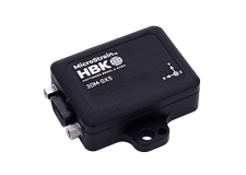
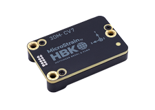
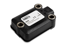
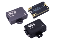
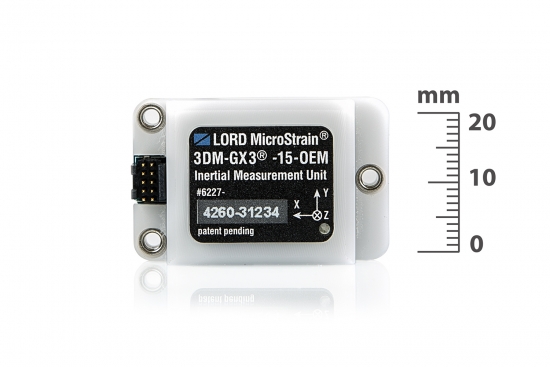
The 3DM-GX3® -15-OEM is a lower cost, miniature, industrial-grade inertial measurement unit (IMU) and vertical reference unit (VRU) in an OEM form factor.
Product Highlights
Product no longer stocked – limited availability
Contact for pricing and lead time--a minimum order quantity may apply
DatasheetBest in Class Performance
Ease of Use
Cost Effective
|
General |
|||
|---|---|---|---|
|
Integrated sensors |
Triaxial accelerometer, triaxial gyroscope, and temperature sensors |
||
|
Data outputs |
Inertial Measurement Unit (IMU) outputs: acceleration, angular rate, deltaTheta, deltaVelocity Computed outputs: attitude estimates (Euler angles, quaternion, orientation matrix) |
||
|
Resolution |
16 bit SAR oversampled to 17 bits |
||
|
Inertial Measurement Unit (IMU) Sensor Outputs |
|||
|
Accelerometer |
Gyroscope |
||
|
Measurement range |
±5 g (standard) ±1.7, and ±50g. (option) |
300°/sec (standard) ±50, ±600, ±1200°/sec (options) |
|
|
Non-linearity |
±0.1 % fs |
±0.03 % fs |
|
|
Bias instability |
±0.04 mg |
18°/hr |
|
|
Initial bias error |
±0.002 g |
±0.25°/sec |
|
|
Scale factor stability |
±0.05 % |
±0.05 % |
|
|
Noise density |
80 µg/√Hz |
0.03°/sec/√Hz |
|
|
Alignment error |
±0.05° |
±0.05° |
|
|
Adjustable bandwidth |
225 Hz (max) |
440 Hz (max) |
|
|
IMU filtering |
Digitally filtered (user adjustable) and scaled to physical inputs; coning and sculling integrals computed at 1 kHz |
||
|
Sampling rate |
30 kHz |
30 kHz |
|
|
IMU data output rate |
1 Hz to 1000 Hz |
||
|
Computed Outputs |
|||
|
Roll and pitch accuracy |
±0.5° (static, typ), ±2.0° (dynamic, typ) |
||
|
Roll and pitch range |
360° about all axes |
||
|
Roll and pitch resolution |
< 0.01° |
||
|
Roll and pitch repeatability |
0.2° (typ) |
||
|
Calculation update rate |
1000 Hz |
||
|
Computed data output rate |
1 Hz to 500 Hz |
||
|
Operating Parameters |
|||
|
Communication |
USB 2.0, TTL serial UART (3.3 V dc, 9,600 bps to 921,600 bps, default 115,200) |
||
|
Power source |
+ 3.1 to + 5.5 V dc |
||
|
Power consumption |
80 mA at 5 V dc (USB) |
||
|
Operating temperature |
-40 °C to +70 °C |
||
|
Mechanical shock limit |
500 g |
||
|
Physical Specifications |
|||
|
Dimensions |
38 mm x 24 mm x 11.6 mm |
||
|
Weight |
11.6 grams |
||
|
Regulatory compliance |
ROHS |
||
|
Integration |
|||
|
Connectors |
Data/power output: Samtec FTSH Series (FTSH-105-01-F-D-K) |
||
|
Software |
MIP™ Monitor, Windows XP/Vista/7/8 compatible |
||
|
Compatibility |
Protocol compatibility with 3DM-RQ1™ and 3DM- GX4® sensor families. |
||
|
Software development kit (SDK) |
MIP™ data communications protocol with sample code available (OS and computing platform independent) |
||
General Documentation
Technical Notes
Mechanical Prints (Uncontrolled)
Using MIP Monitor software, to reset the device to the factory defaults:
This process does not erase any hard and soft iron calibration that may be on the device.
The Hard and Soft Iron Cal software we provide must be used to do that.
The main difference between single byte (SB) and MIP is as follows:
The reason we created MIP was the higher reliability for communications and control, plus the ability to have custom data messages. SB was prone to phantom commands in a noisy environment. In addition, SB had a limited number of data combinations available.
To move code from Single Byte to MIP with simple applications is fairly painless if you follow some guidelines.
The ECCN is 7A994.
From time to time, MicroStrain releases firmware upgrades for its 3DM-GX3® inertial sensors. These firmware upgrades represent operating improvements, new functions, etc. In most cases, the user may download these upgrades and perform the upgrade using a simple step-by-step process. This technical note describes which firmware upgrades may be accomplished by the user and which firmware upgrades must be done at the factory. Familiarity with 3DM-GX3® operation is assumed. The upgrade procedure employs a Microsoft Windows computer and the Microsoft HyperTerminal utility.
Many inertial applications incorporate dataloggers. The datalogger can take many forms: hardware or software, analog or digital, simple or complex, and/or combinations of all. For our purposes, let’s work through a simple-digital-software datalogger. In this case, datalogger software is installed on a computer. The inertial sensor is connected to the computer via an RS-232 communication interface. The inertial sensor is pre-programmed to automatically send data when powered. The computer receives the stream of data and the datalogger software continuously records the stream to a data file.
The LORD MicroStrain 3DM-GX3 inertial sensor family allows the user to pre-program the inertial sensor so that it continuously outputs specific data packets at specific sampling rates each time it is powered on. This functionality facilitates integration of the inertial sensor with other equipment and systems. For example, connection of the 3DM-GX3 inertial sensor to a datalogger becomes quite easy. The user pre-programs the 3DM-GX3 data output settings on his desktop, connects the 3DM-GX3® to the datalogger’s RS-232 port, powers the 3DM-GX3, and the datalogger records the inertial data. This technical note assumes some familiarity with your particular 3DM-GX3 inertial sensor and its accompanying MIP Monitor (Windows-based) software.
|
Static accuracy |
±0.5° pitch, roll, heading typical for static test conditions |
|
Dynamic accuracy |
±2.0° pitch, roll, heading for dynamic (cyclic) test conditions and for arbitrary angles |
Important note: Unlike the -25, the -15 does not contain magnetometers. Magnetometers measure Earth's magnetic fields and provide the AHRS with a reference to produce an accurate heading. In the -15, the heading is accurate from moment to moment but drifts over time and should not be relied upon.
Here is a link to a detailed technical note: http://files.microstrain.com/Orientation%20Conversion%20formulas.pdf
Yes. We have had good success with several types of off-the-shelf USB to serial port adaptors, such as those from IOGear and Keyspan, which may be purchased through any of the electronics products distributors.
Here is a link to a detailed technical note: http://files.microstrain.com/3DM-GX3-25_OEM_Footprint_and_Connector.pdf
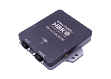
The standard unit uses a specialized Ulti-Mate brand micro-DB9. This technical note contains more details: http://files.microstrain.com/TN-I0023_Inertia-Link_3DM-GX2_3DM-GX3_Pin-Outs.pdf
The OEM unit uses a Samtec FTSH-105-01-F-D-K. This technical note contains more details: http://files.microstrain.com/3DM-GX3-25_OEM_Footprint_and_Connector.pdf
LORD MicroStrain® suggests that you purchase additional connectors with your order.
The 3DM-GX3 USB and RS-232 communication interfaces are built to satisfy the standard USB-IF and EIA specifications. LORD MicroStrain® provides 6 foot cables as standard. Many techniques can be used to extend the length of the communication interfaces including powered USB hubs, USB boosters, RS-232 extenders, etc.
The 3DM-GX3 is calibrated at the factory. The user is also provided with Hard and Soft Iron Calibration software to field calibrate the GX3 in situ. This video further describes the function: http://www.microstrain.com/video/hard-soft-iron-calibration
Important note: Hard and soft iron calibration is not required for the 3DM-GX3-15 and the 3DM-GX315 OEM. These units do not contain magnetometers.
From time to time the 3DM-GX3 may need recalibration. For example, as a result of coming in contact with magnetic influences (magnets, motors, etc.), residual magnetism may be picked up by the on-board components which will alter the calibration. Another example: the 3DM-GX3 receives a severe shock, slightly altering the position of the circuit boards in relation to the enclosure, again altering the calibration. In these cases the unit should be returned to the factory for recalibration.
Yes. Any number of units can be operated by a host at the same time. Several considerations surround this implementation (primarily computing power) and we suggest that you discuss your requirements with LORD MicroStrain® sales or a support engineer.
For the standard units, here is a link to a detailed technical note: http://files.microstrain.com/TN-I0023_Inertia-Link_3DM-GX2_3DM-GX3_Pin-Outs.pdf
For the OEM units, here is a link to a detailed technical note: http://files.microstrain.com/3DM-GX3-25_OEM_Footprint_and_Connector.pdf
Yes, there are no limitations. However, if a user requires a ‘zeroing’ of the axes, this must be done in the user’s external application. Good practice dictates that the orientation matrix be used to calculate such zeroing. Please also be aware of the mathematical singularity in Euler angles.
The user should be aware that the Euler angle formulation in general contains a mathematical singularity at Pitch = +90 or –90 degrees. In practice, poor numerical results will be present if the Pitch angle exceeds +/-70 degrees. In applications where the Pitch angle cannot be guaranteed to exceed these values, it is recommended that the orientation matrix output be utilized instead.
Yes. The sampling rates are user adjustable.
For the -15 and -25, the user may set the sampling rate at up to 1000 Hz depending on the data quantity.
For the -35, the user may set the AHRS sampling rate up to 1000 Hz depending on the data quantity and the GPS sampling rate up to 4 Hz.
For the -45, the user may set the Navigation sampling rate up to 100 Hz.
The baud rate is user adjustable and may be set to 9600, 19200, 115200 (default), 230400, 460800, and 921600.
Yes. The presence of strong magnetic fields or large magnetic materials will distort Earth’s weak local magnetic field and this will influence the on-board magnetometers. A hard and soft iron calibration software utility is provided to field calibrate the 3DM-GX3-25, 3DM-GX3-25 OEM, 3DM-GX3-35 and 3DM-GX3-45.
The 3DM-GX3-15 and 3DM-GX3-15 OEM do not contain magnetometers and are not affected by hard and/or soft iron interference.
The following orientation outputs formats are available:
A detailed description of these outputs can be found in the Data Communications Protocol manual of each product.
The standard units support both USB and RS-232 interface.
The OEM units support both USB and TTL.
Yes. We provide a complete data communications protocol manual which describes in detail each and every command and response that is available with the device. Applications may be developed in any programming environment (C, VB, LabVIEW, Linux, Matlab, etc.) which supports serial communication.
We provide a general application for Microsoft XP/Vista/Win 7 operating systems that configures, reads, displays and saves data generated by the device. This application (MIP Monitor) supports both the USB and RS-232 communication interfaces.
When you initially purchase a 3DM-GX3, a starter kit (SK) provides you with everything you need to get started! SKs include a 3DM-GX3 module, communication and power cables, software, manuals and GPS antenna if applicable. In subsequent purchases you may only require additional modules or other individual components. Several communication interfaces are available creating several starter kit variations.
No. There is no upgrade path.
© HBK, Inc 2023
Privacy Statement |
SensorCloud™ Services Agreement |
Terms & Conditions of Sale